 Store

 EN
 CN
 VI
 IT
 ES
 TH
 JA
 PT
 MS
 KO
 FR
 DE
 ID
In a miniature motion system, motor control is not simply a matter of applying voltage and setting a target speed. As motor dimensions decrease and operating speeds increase, the relationship between current, torque, heat generation, and mechanical load becomes increasingly important. A small change in operating conditions can affect motion consistency, especially when the motor is installed inside a compact device with limited space for electronics and heat dissipation.
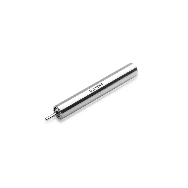
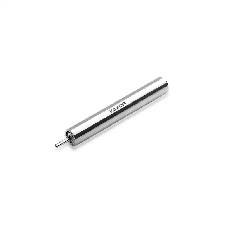
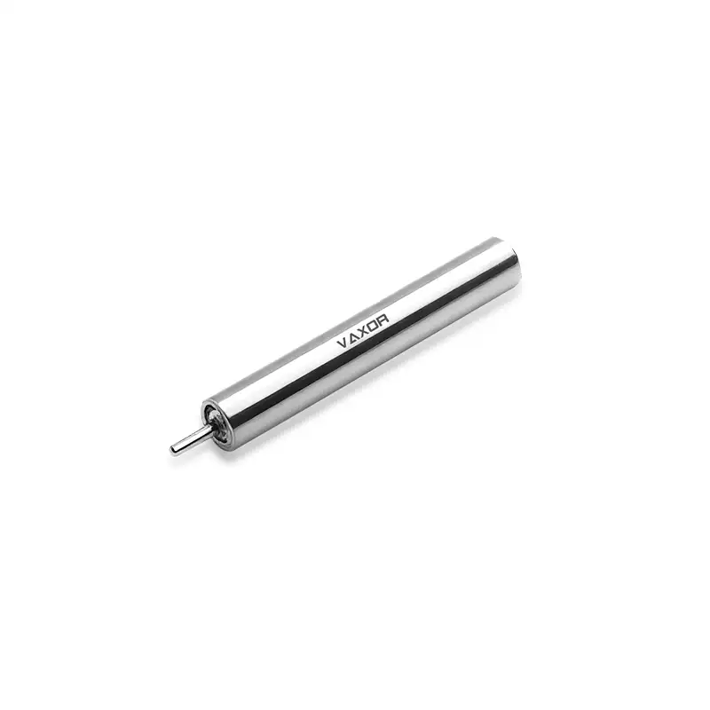
This is particularly relevant to a 4mm brushless coreless motor. Designed for applications where installation space is extremely restricted, the φ4mm Ultra-micro Brushless Coreless Motor combines a 4mm diameter with a nominal speed of 30,000 rpm and a no-load speed of 55,000 rpm. To use this type of motor effectively, engineers need a current-control strategy that matches the electrical drive system to the required mechanical output.
Why Current Control Matters in High-Speed Micro Motors
Motor current is closely related to the electromagnetic torque generated by a motor. When a motor encounters a higher mechanical load, it generally requires more torque to maintain its operating condition. Current control allows the drive system to regulate the electrical input according to the required output rather than relying only on a fixed voltage command.
For a high-speed miniature motor, this is important for several reasons.
First, the motor may operate under changing loads. A precision mechanism can move freely during one part of its working cycle and encounter greater resistance during another. Without suitable current regulation, the motor may experience inconsistent acceleration or fail to maintain the required motion.
Second, current affects electrical losses and heat generation. Excessive current can increase winding losses, placing additional thermal stress on a motor that has very little physical space for heat dissipation.
Third, current limits help protect the motor and its driver during abnormal conditions, such as a blocked output shaft or unexpected mechanical resistance. These limits should be established using the motor's actual electrical specifications and the thermal capacity of the complete assembly.
Using the Torque Constant to Estimate Current Demand
The torque constant is one of the most useful parameters when developing a current-control strategy. It describes the relationship between motor current and the torque generated by the motor under the specified operating convention.
The G04P-VW00-QZ-1 model has a torque constant of 0.82 mNm/A. In a simplified motor model, the relationship can be expressed as:
Torque = Torque Constant × Current
Using this relationship, engineers can estimate the current associated with a required torque:
Current = Required Torque ÷ Torque Constant
For example, if a mechanism requires a theoretical motor torque of 0.20 mNm, the estimated current based on the stated torque constant would be approximately 0.244 A. This is a preliminary calculation, not a guaranteed operating current. Actual current demand can be affected by the motor's electrical characteristics, drive method, operating speed, temperature, and mechanical losses.
The nominal torque of this motor is specified as 0.38 mNm, while the stalling torque is 0.76 mNm. These values provide useful reference points when evaluating the motor's output capability. However, the stalling torque should not be treated as a continuous operating target. A motor held at or near stall can experience substantial current and heat generation.
For the φ4mm Ultra-micro Brushless Coreless Motor, the 0.82 mNm/A torque constant offers a starting point for estimating torque demand and developing current commands. Final control parameters should be verified against the manufacturer's electrical data and measured performance.
Selecting a Suitable Current-Control Method
The appropriate control method depends on the motor driver, application requirements, and available feedback signals. Several approaches can be considered during system development.
Current Limiting
Current limiting establishes an upper boundary for the electrical current supplied to the motor. When the measured or estimated current reaches that boundary, the driver adjusts its output to prevent further increases.
This approach is useful in compact mechanisms where unexpected resistance or mechanical blockage could otherwise place excessive stress on the motor. The current limit should be selected according to the motor's permitted operating conditions, not simply set as high as the driver can support.
For miniature equipment, the limit also needs to account for the operating duration. A current level that is acceptable for a short acceleration event may not be suitable for continuous operation.
Closed-Loop Current Regulation
Closed-loop current regulation uses current feedback to compare the actual current with a target value. The controller then adjusts the drive output to reduce the difference between them.
Compared with a basic voltage command, this method provides more direct control over the electrical input. It can be useful when the motor operates under changing mechanical loads or when repeatable torque output is important.
The implementation depends on the driver's current-sensing method, control bandwidth, and supported commutation architecture. Engineers should confirm that the selected driver is compatible with the motor before defining the control loop.
PWM-Based Drive Adjustment
Pulse-width modulation (PWM) is commonly used in motor drive electronics to regulate the voltage applied to a motor. By changing the duty cycle, the driver adjusts the effective electrical input.
PWM and current control are related but are not interchangeable. A PWM command determines the switching behavior of the drive stage, while current regulation uses current feedback or an appropriate current-estimation method to control the actual electrical current.
For a high-speed miniature motor, PWM frequency, switching behavior, and driver response should be considered together. The selected settings need to be validated with the actual motor and control electronics rather than assumed from general motor-drive guidelines.
Matching Current Commands to Speed and Mechanical Load
The G04P-VW00-QZ-1 operates at a specified nominal voltage of 6 V. Its nominal speed is 30,000 rpm, and its no-load speed is 55,000 rpm. These figures describe different operating conditions and should be considered when defining the control strategy.
At no load, the motor can reach a higher speed because it is not required to provide significant mechanical output torque. When connected to a mechanism, the motor must overcome friction, inertia, and external resistance. Its operating point therefore changes according to the load and electrical input.
A practical control system should distinguish between speed requirements and torque requirements. For example, a miniature pump may need to maintain a relatively stable operating speed as fluid resistance changes. A precision instrument may instead require controlled acceleration and repeatable positioning of a small mechanical component.
In either case, the current command should be developed around the actual load profile. Applying a fixed high current throughout the operating cycle may create unnecessary heat and energy consumption. A better approach is to determine the current required during startup, acceleration, steady operation, and changes in mechanical resistance.
Managing Current and Heat in a 4mm Motor
Thermal management is a critical consideration when working with motors as small as 4mm in diameter. The motor's limited physical volume restricts the available surface area for heat transfer, while the surrounding device housing may further limit airflow.
Electrical losses increase with current. As a result, repeatedly operating at high current can raise the motor temperature, particularly when the mechanism has frequent starts, stops, or load changes.
Engineers should therefore evaluate the complete duty cycle rather than looking only at the motor's maximum output. Important factors include operating duration, acceleration frequency, average load, peak load, and the time available for cooling between movement cycles.
Current limits should be tested under realistic installation conditions. A motor operating in an open test fixture may have different thermal behavior from one installed inside a sealed precision instrument. Temperature measurements on the assembled device can provide a more reliable basis for setting continuous operating limits.
The 4mm brushless coreless motor is intended for space-constrained applications, but compact dimensions do not remove the need for thermal validation. The motor, driver, wiring, and mechanical assembly should be evaluated as one system.
Practical Steps for Developing a Current-Control Strategy
A structured test process can help engineers establish suitable control parameters before integrating the motor into production equipment.
Confirm the electrical specifications. Obtain the motor's rated current, winding resistance, permitted current range, and driver requirements. The 6 V voltage rating and 0.82 mNm/A torque constant alone are not sufficient to define every current limit.
Identify the mechanical load profile. Measure or estimate the torque required during startup, acceleration, steady operation, and load changes.
Select a compatible driver. Confirm that the driver supports the motor's electrical configuration, commutation requirements, current sensing, and intended operating speed.
Set preliminary current limits. Use manufacturer data and initial test results to establish safe limits for continuous and transient operation.
Test under representative conditions. Record current, speed, temperature, and operating stability across the expected load range.
Refine the control parameters. Adjust current limits and control-loop settings based on measured performance, ensuring that the motor does not remain under excessive load for extended periods.
This process helps prevent a common integration problem: selecting a driver based only on voltage compatibility while overlooking current regulation and thermal behavior.
VAXOR's Approach to Ultra-micro Motor Development
Founded in 2024 and headquartered in Suzhou, China, VAXOR develops micro joint actuators and ultra-micro coreless motors for robotics, medical devices, precision instruments, and intelligent equipment.
Its technical roadmap focuses on compact size, high performance, and scalable production. The company's multidisciplinary team brings together experience in motor design, precision manufacturing, structural engineering, robotics control, and intelligent manufacturing. This combination supports development from prototype validation and pilot production through to batch delivery.
VAXOR also works with axial-flux motor technology, PCB and FPCB winding, optimized electromagnetic design, and miniature reduction mechanisms to develop compact motion solutions. These technologies address the engineering demands of miniature drive systems, where available space, output requirements, response characteristics, and manufacturing consistency all need to be considered together.
The φ4mm Ultra-micro Brushless Coreless Motor, model G04P-VW00-QZ-1, is specified with a 6 V voltage, 30,000 rpm nominal speed, 0.38 mNm nominal torque, and 1.7 g weight. Its 4mm diameter makes it suitable for design evaluations involving extremely limited installation space.
Building a More Reliable Drive System
Current control is an important part of integrating high-speed miniature motors into precision equipment. The torque constant helps engineers estimate the relationship between current and output torque, while current limiting, feedback regulation, and PWM-based drive adjustment provide different ways to manage electrical input.
For a 4mm motor operating at tens of thousands of revolutions per minute, the control strategy must also account for mechanical load, thermal conditions, driver compatibility, and the actual duty cycle. Testing the complete assembly is essential because electrical and mechanical behavior can change significantly after installation.
With its compact 4mm diameter and defined speed and torque specifications, the φ4mm Ultra-micro Brushless Coreless Motor provides a drive option for advanced miniature applications. By matching current control to verified motor data and real operating requirements, engineers can make better use of its capabilities in precision instruments, medical devices, and other space-constrained systems. VAXOR continues to develop micro-drive technologies for applications where compact dimensions and dependable motion performance are essential.