 Store
Store
 EN
EN CN
CN VI
VI IT
IT ES
ES TH
TH JA
JA PT
PT MS
MS KO
KO FR
FR DE
DE ID
IDWhen a device is already measured in millimeters, adding even a small amount of motor weight can affect the entire mechanical design. The motor may influence how much supporting structure is required, how the moving assembly behaves, and how much space remains for electronics, wiring, bearings, and other components. This is why weight should not be treated as a secondary specification in miniature motion systems.
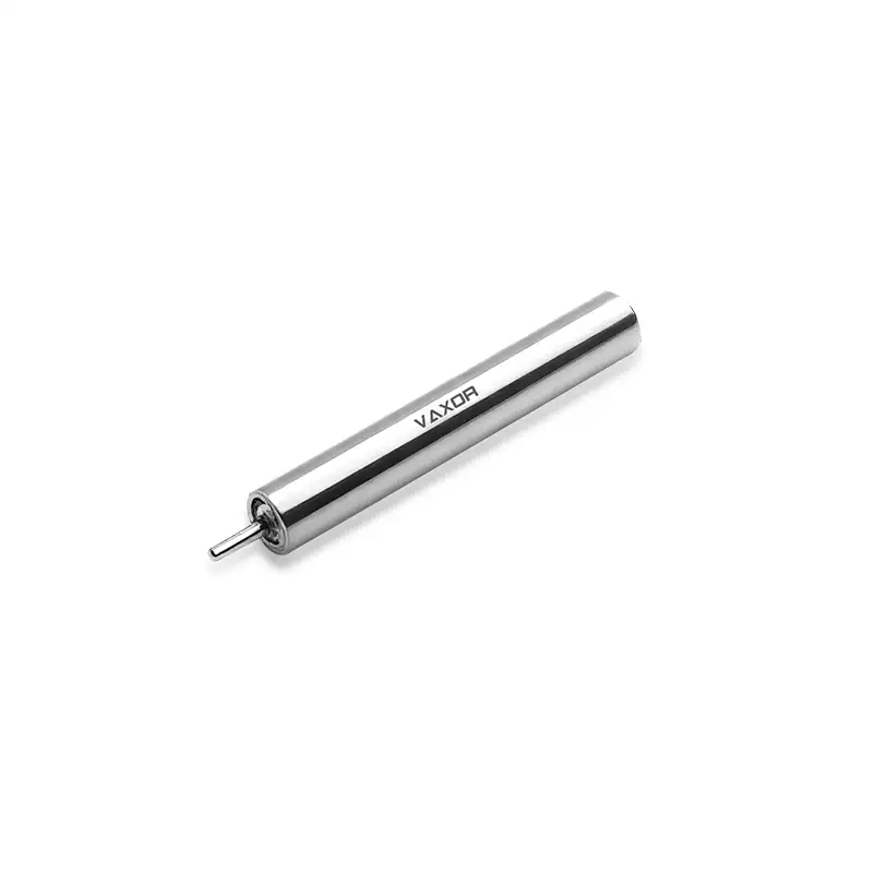
At just 1.7g, the φ4mm Ultra-micro Brushless Coreless Motor is designed around this problem. Its 4mm diameter allows it to fit into highly space-constrained mechanisms, while its low mass helps engineers keep the overall moving assembly compact. For medical devices, precision instruments, and other miniature equipment, this combination can make a practical difference during mechanical integration.
Why Motor Weight Matters in Miniature Equipment
In a conventional motorized system, a difference of a few grams may have little impact on the overall structure. In a miniature mechanism, the situation is different.
When the motor accounts for a meaningful portion of the moving mass, its weight can affect the support structure, actuator response, balance, and available space for other components. Engineers may need to reinforce brackets or redesign the mounting arrangement simply because the motor is heavier than the surrounding mechanism can comfortably accommodate.
A 1.7g motor gives designers more flexibility. It can help reduce the mechanical burden on compact assemblies and make it easier to position the drive unit close to the moving part.
This is particularly relevant when the motor is installed inside a handheld instrument, miniature actuator, medical mechanism, optical system, or other equipment where every gram and millimeter must be considered together.
4mm Diameter Changes the Integration Approach
Low weight alone does not solve the packaging problem. The motor also needs to physically fit into the available space.
The φ4mm Ultra-micro Brushless Coreless Motor has a diameter of only 4mm, making it suitable for mechanisms where a larger motor simply cannot be installed. Instead of enlarging the housing to accommodate the drive unit, engineers can work with a motor that is already designed around an extremely small radial footprint.
This can be useful when several components need to occupy the same area. A smaller motor leaves more room for sensors, transmission components, control electronics, wiring, or structural features.
For miniature equipment, this can change the design process from “How can we make the enclosure larger?” to “How can we arrange the existing components more efficiently?”
That distinction matters in products where the external dimensions are already constrained by ergonomics, installation requirements, or the size of the operating mechanism.
1.7g Does Not Mean Low Performance
A common concern with ultra-light motors is whether reducing size and weight also means sacrificing useful output.
The G04P-VW00-QZ-1 is specified for a 6V operating voltage, with a no-load speed of 55,000 rpm and a nominal speed of 30,000 rpm. Its nominal torque is 0.38 mNm, while the listed stalling torque reaches 0.76 mNm.
These figures show why the motor should be evaluated as a complete drive component rather than by weight alone.
The 30,000 rpm nominal speed provides a useful reference for applications that require fast rotational motion under operating conditions. The 55,000 rpm no-load speed indicates the motor's high-speed capability when mechanical load is not applied.
For designers, the important question is therefore not simply whether a motor is light. It is whether the motor can provide the required speed and torque without forcing the rest of the system to become larger or heavier.
Understanding the Difference Between No-Load and Nominal Speed
The difference between 55,000 rpm no-load speed and 30,000 rpm nominal speed is important when selecting a motor.
No-load speed describes motor rotation without the mechanical load that exists during normal operation. Once the motor drives a mechanism, the actual operating point changes according to the load, current, transmission arrangement, and system requirements.
Nominal speed provides a more practical reference for application design because it represents the motor's specified operating condition rather than its maximum unloaded rotational speed.
For an engineer designing a miniature mechanism, using 55,000 rpm as the expected working speed could lead to an incorrect mechanical design. The 30,000 rpm nominal figure is more useful when evaluating the motor against the intended operating range.
This distinction becomes especially important when selecting bearings, transmission components, lubrication methods, and control parameters for high-speed miniature mechanisms.
Where Ultra-Lightweight Motors Can Be Useful
A 1.7g motor becomes especially valuable when the surrounding system is also designed for minimum size and weight.
Medical devices are one example. Internal mechanisms may need to perform controlled movement while leaving room for sensing, electronics, and structural components. Reducing motor mass can make packaging easier without requiring the entire mechanism to be enlarged.
Precision instruments can have similar requirements. Optical, measurement, inspection, and laboratory mechanisms often combine multiple small components inside a limited enclosure. A 4mm motor provides a compact drive option when conventional motors would consume too much installation space.
Other miniature applications can also benefit from the combination of small diameter and low mass. The suitability depends on the required torque, speed, operating cycle, power supply, and mechanical load, but the basic design advantage remains the same: less motor mass and a smaller radial footprint give engineers more freedom when arranging the system.
Matching 0.38 mNm Torque to the Mechanism
The 0.38 mNm nominal torque should be evaluated against the actual mechanical load rather than treated as an isolated performance number.
For example, if the motor is directly connected to a small rotating component, engineers need to consider the component's inertia, friction, acceleration requirement, and operating speed. If a transmission mechanism is used, the transmission ratio and efficiency also become part of the calculation.
The 0.76 mNm stalling torque provides another useful reference, but stall conditions should not be treated as a normal operating point. A practical design should remain within the appropriate operating range and avoid relying on prolonged stall operation.
The torque constant of 0.82 mNm/A can also help engineers understand the relationship between motor current and torque during system design. This becomes useful when the motor needs to be integrated with a dedicated driver and power-management architecture.
In other words, the value of a miniature motor comes from how its specifications fit the complete mechanism, not from one specification viewed independently.
Why Coreless Construction Matters in Space-Constrained Designs
Coreless motor construction is particularly relevant when engineers are looking for a compact drive with high-speed characteristics and low moving mass.
Without a conventional iron core in the rotor, the rotating assembly can be designed with a low-inertia structure. For applications involving frequent acceleration and deceleration, this characteristic can be important because the drive does not need to move unnecessary rotor mass.
That makes the combination of a compact 4mm diameter and 1.7g total weight particularly relevant to miniature motion systems where rapid response and limited installation space are both design requirements.
The goal is not simply to make the motor smaller. The goal is to reduce the size and mass of the drive without losing the performance needed by the application.
Designing Around the Motor Instead of Around the Enclosure
For miniature products, motor selection is often part of the mechanical architecture rather than a component chosen at the end of the design process.
A motor with a 4mm diameter can influence the shape of the internal mechanism, mounting position, shaft arrangement, surrounding clearances, and wiring path. Its 1.7g weight can also affect the total mass of a moving assembly.
This is where φ4mm Ultra-micro Brushless Coreless Motor becomes relevant as a design option. Its specifications provide engineers with a starting point for evaluating whether an ultra-small motor can meet the application's mechanical and electrical requirements before the enclosure and internal structure are finalized.
For OEM and custom equipment development, this early-stage evaluation can prevent later redesigns caused by an oversized drive component.
Building Smaller Motion Systems with VAXOR
Miniaturization requires more than reducing one component. Motor design, precision manufacturing, mechanical integration, control, and production consistency all have to work together.
VAXOR focuses on micro-drive technologies for robotics, medical devices, precision instruments, and intelligent equipment. Its engineering capabilities cover motor design, precision manufacturing, structural design, robotics control, and intelligent manufacturing, supporting the transition from prototype validation to pilot production and batch delivery.
For engineers working on space-constrained equipment, the practical value of a 1.7g motor is therefore not simply the number on the specification sheet. It is the additional design freedom created when a high-speed drive can occupy only 4mm of diameter and add very little mass to the system.
The φ4mm Ultra-micro Brushless Coreless Motor brings together a 4mm diameter, 1.7g weight, 30,000 rpm nominal speed, 0.38 mNm nominal torque, and 6V operating voltage in a format intended for extreme space constraints. For miniature mechanisms where size, weight, speed, and integration space all compete for priority, these specifications provide a practical basis for evaluating a smaller drive architecture.