 Store
Store
 EN
EN CN
CN VI
VI IT
IT ES
ES TH
TH JA
JA PT
PT MS
MS KO
KO FR
FR DE
DE ID
IDIn miniature drive systems, achieving high rotational speed within a limited installation space is only part of the engineering challenge. The motor must also deliver sufficient torque under load, respond consistently to changes in operating conditions, and work within the electrical and mechanical limits of the complete device. These requirements become particularly important in compact equipment, where even small changes in friction, load inertia, or power consumption can affect overall performance.
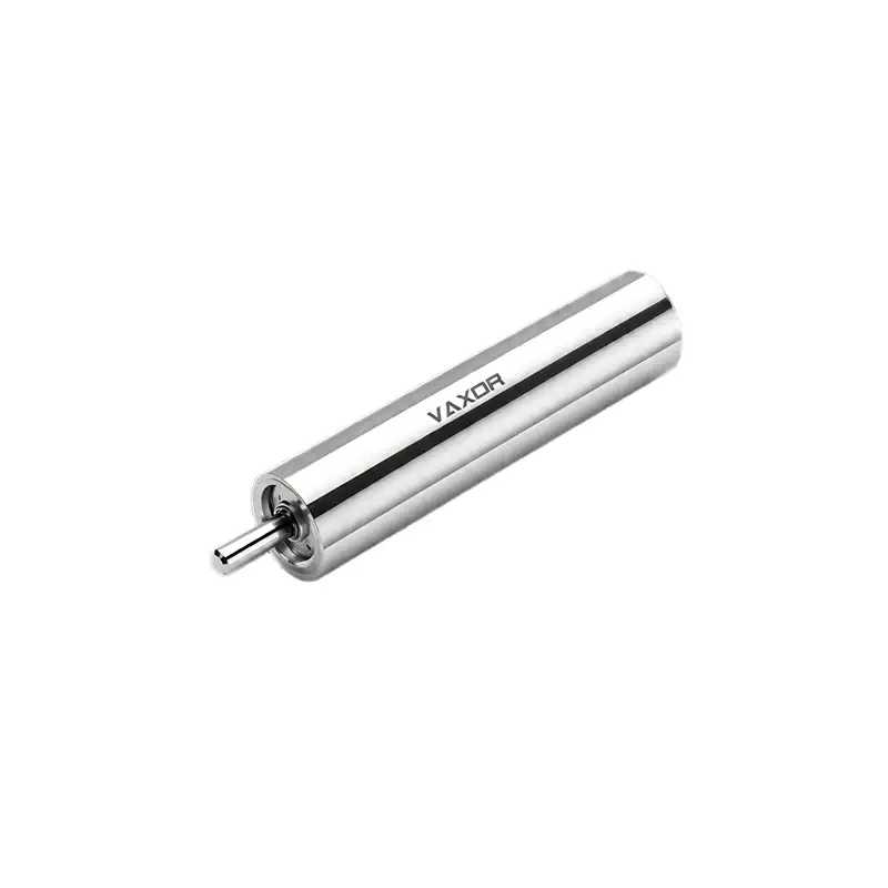
The φ6mm Ultra-micro Brushless Coreless Motor is designed for applications that require high-speed rotation in a compact footprint. Model G06P-VW00-QZ-1 operates at a rated voltage of 12 V, with a no-load speed of 63,000 rpm and a nominal speed of 45,000 rpm. Its nominal torque is 0.49 mNm, while its listed stall torque is 0.98 mNm. These specifications provide a starting point for evaluating the motor's suitability for miniature mechanisms, precision instruments, and other space-constrained drive applications.
What Does 63,000 RPM Mean for a Miniature Motor?
A rotational speed of 63,000 rpm represents a demanding operating capability for a motor with a diameter of just 6 mm. At this scale, the motor can be considered for mechanisms that require rapid rotation while keeping the drive assembly compact.
However, the meaning of a speed specification depends on the conditions under which it is measured. No-load speed describes the motor's rotational speed when it operates without an external mechanical load. It does not indicate the speed that the motor will maintain after being connected to a gear train, pump, rotating element, or other driven component.
For the G06P-VW00-QZ-1, the listed no-load speed is 63,000 rpm, while the nominal speed is 45,000 rpm. The difference is important during system design because the motor must supply torque to overcome the load and the losses associated with the drive mechanism.
Engineers should therefore avoid selecting a motor based solely on its maximum or no-load speed. Instead, they should determine the operating speed required by the application and assess whether the motor can maintain that speed under the expected load.
For example, a miniature rotating mechanism may require rapid acceleration but operate at a lower speed once it reaches its working condition. Another device may need to maintain a relatively stable rotational speed while its mechanical resistance changes. These two applications may require different control strategies even if their target speeds are similar.
Understanding the Relationship Between Speed and Torque
Speed and torque are closely related when selecting a motor for a real application. A motor may rotate very quickly without a load, but the speed generally decreases when mechanical resistance increases. The actual relationship depends on the motor's performance characteristics, electrical supply, controller, and operating conditions.
The φ6mm Ultra-micro Brushless Coreless Motor has a nominal torque of 0.49 mNm and a listed stall torque of 0.98 mNm. Nominal torque is relevant when evaluating the specified operating condition, while stall torque describes the torque associated with a stationary rotor under the applicable test conditions.
These values should not be treated as interchangeable. Stall conditions can produce substantial current and heat, so stall torque is not a suitable target for continuous operation unless the manufacturer explicitly specifies otherwise.
When matching the motor to a miniature drive load, engineers should first estimate the torque required by the driven mechanism. This estimate should account for friction, acceleration, transmission losses, and changes in mechanical resistance during operation.
It is also important to consider startup requirements. Some mechanisms need a higher initial torque to overcome static friction or accelerate a rotating load. Others have relatively low startup resistance but require stable operation over a wide speed range.
A suitable motor selection should therefore be based on the application's complete speed and torque requirements, rather than on one specification in isolation.
Matching Motor Speed to Load Inertia
Load inertia is an important consideration in high-speed miniature drive systems. It describes how strongly a rotating object resists changes in rotational speed. A motor connected to a lightweight rotor may accelerate differently from the same motor connected to a heavier component, even when both systems have similar steady-state torque requirements.
This difference becomes especially relevant when an application requires frequent starts, stops, or speed changes. The motor must produce enough torque to accelerate the load within the required time while remaining within its operating limits.
For a high-speed motor, engineers should evaluate several factors:
The inertia of the driven component and any connected transmission parts.
The required acceleration and deceleration time.
The frequency of repeated starts and stops.
The mechanical friction present during startup and steady operation.
The allowable current, temperature, and vibration levels.
The 63,000 rpm no-load speed of the G06P-VW00-QZ-1 motor may be relevant to applications with demanding rotational-speed requirements, but the final operating point should be verified with the actual mechanical load.
Prototype testing is particularly useful at this stage. Engineers can record acceleration time, steady-state speed, current consumption, and temperature under representative conditions. These measurements help establish whether the selected motor can meet the application requirements without excessive electrical or mechanical stress.
Electrical Selection for a 12V Brushless Motor
The electrical system plays a direct role in motor performance. Voltage, current capacity, controller compatibility, and the quality of the power supply can all affect startup behavior and rotational stability.
Model G06P-VW00-QZ-1 is specified for 12 V operation. When selecting a suitable driver, engineers should confirm that the controller supports the motor's electrical characteristics and the required speed range. The driver must also be able to handle the expected operating current and any transient demands associated with startup or acceleration.
The motor's torque constant is listed as 1.05 mNm/A. This parameter describes the relationship between motor current and the torque generated under the relevant operating assumptions. It can help engineers estimate the current associated with a required torque, but actual performance also depends on losses and the motor's operating conditions.
A practical electrical evaluation should include the following checks:
Confirm the rated voltage and permitted supply conditions.
Verify driver compatibility with the brushless motor's commutation requirements.
Check current limits during startup and acceleration.
Evaluate speed control and response to changing loads.
Measure current consumption at representative operating points.
Confirm that wiring and connectors are suitable for the intended electrical load.
A controller should not be selected only because it supports a nominal 12 V supply. Its control method, current capability, and operating-speed range must also match the motor and the application.
Why Compact Size Matters in Miniature Drive Systems
A motor diameter of 6 mm creates opportunities for integration into devices where space is limited. However, reducing motor size also places greater emphasis on mechanical layout, load matching, heat management, and assembly precision.
The φ6mm Ultra-micro Brushless Coreless Motor weighs 3.75 g, making its mass an important consideration when designing lightweight drive assemblies. In compact mechanisms, the motor's dimensions and weight can influence the arrangement of supporting structures, bearings, transmission components, and electrical connections.
Potential applications include miniature rotary mechanisms, precision instruments, compact automation devices, and other systems that require a small motor with high rotational speed. Suitability depends on the specific load, duty cycle, available space, and required service life.
Designers should also assess the motor's mounting arrangement and the alignment of the driven components. Poor alignment or excessive mechanical friction can increase the load on the motor, reduce achievable speed, and introduce unwanted vibration.
A compact motor should therefore be evaluated as part of the complete drive assembly. The objective is not simply to fit a small motor into the available space, but to ensure that the motor, transmission, bearings, controller, and driven load work together as intended.
Managing Heat During High-Speed Operation
High rotational speed can create additional thermal challenges, particularly when a miniature motor operates under load or performs repeated acceleration cycles. Electrical losses and mechanical losses contribute to heat generation, while the limited surface area of a small motor can restrict heat dissipation.
The actual temperature rise depends on factors such as operating current, load torque, ambient temperature, duty cycle, mounting structure, and available airflow. A motor that performs adequately during a short bench test may behave differently during extended operation inside a compact enclosure.
Engineers should evaluate the intended duty cycle before approving a design. Continuous rotation, intermittent operation, frequent acceleration, and repeated stall events impose different demands on the motor and controller.
Useful validation measurements include winding or housing temperature where measurable, current consumption, operating speed, and changes in performance over time. Testing should use the intended power supply, controller, mounting arrangement, and representative mechanical load.
Stall conditions deserve particular attention. Since a stationary rotor cannot perform the intended rotational work, prolonged stall operation may create excessive heat and electrical stress. Suitable current limiting and fault-handling strategies can help protect the drive system.
These checks are necessary to establish the appropriate operating limits for the finished device. The rated and no-load speed values alone do not define the motor's permissible continuous operating duration.
Testing Drive Stability Under Real Operating Conditions
Stable motor operation depends on more than achieving a target rotational speed. Variations in mechanical resistance, power supply conditions, controller behavior, and assembly quality can affect speed consistency and response.
A structured prototype test can help identify these issues before production. Begin by measuring the motor's speed and current without an external load, then repeat the measurements with a representative load attached. Next, evaluate startup response, acceleration, and performance when the load changes.
For applications requiring frequent speed adjustments, engineers should also assess how quickly the system responds to control commands and whether it exhibits unwanted oscillation or speed variation.
Mechanical inspection is equally important. Check mounting rigidity, shaft alignment, transmission friction, and vibration under operating conditions. If the motor is integrated into a larger mechanism, the entire assembly should be tested because resonances or mechanical imbalance may not be apparent in an isolated motor test.
For the φ6mm Ultra-micro Brushless Coreless Motor, the combination of 63,000 rpm no-load speed, 45,000 rpm nominal speed, and 0.49 mNm nominal torque provides useful initial selection data. Actual drive stability must still be confirmed with the intended controller, mechanical load, and operating cycle.
Working with a Micro-Drive Technology Partner
Selecting a miniature motor often requires coordination between electrical design, mechanical engineering, and application development. A supplier with experience in these areas can help clarify specifications and support the transition from initial evaluation to prototype validation and production planning.
VAXOR was founded in 2024 and is headquartered in Suzhou, China. The company develops micro joint actuators and ultra-micro coreless motors for robotics, medical devices, precision instruments, and intelligent equipment.
Its technology roadmap combines axial-flux motor technology, PCB/FPCB winding, electromagnetic design, and miniature reduction mechanisms to address the requirements of compact motion systems. VAXOR also describes a multidisciplinary engineering team covering motor design, precision manufacturing, structural design, robotics control, and intelligent manufacturing.
For a motor selection project, buyers should provide the intended operating speed, required torque, supply voltage, available installation space, duty cycle, and expected operating environment. Where possible, they should also share details of the driven load and the desired acceleration response.
These details make it easier to assess whether a motor's published specifications match the application. Buyers should request the relevant performance curves, operating limits, driver recommendations, and test information needed to validate the design.
A Practical Checklist for Selecting a 6mm High-Speed Motor
Before finalizing a motor for a miniature drive system, confirm the following:
Speed requirements: Distinguish between no-load speed and the required speed under load.
Torque requirements: Estimate steady-state torque, startup torque, and acceleration demands.
Electrical compatibility: Verify the 12 V supply, driver type, current capacity, and control method.
Mechanical integration: Check available space, mounting, alignment, and load inertia.
Thermal performance: Test current consumption and temperature under the intended duty cycle.
Operating stability: Evaluate speed variation, vibration, and response to load changes.
Validation data: Confirm the manufacturer's operating limits and relevant performance documentation.
A 63,000 rpm specification can make a 6 mm motor worth evaluating for high-speed miniature mechanisms, but successful selection depends on how the motor performs at the application's actual working point. By assessing speed, torque, current, heat, and mechanical integration together, engineers can make a more reliable decision before committing to a final drive design.
The φ6mm Ultra-micro Brushless Coreless Motor, model G06P-VW00-QZ-1, offers a defined set of speed, torque, voltage, and weight specifications for this evaluation. With application requirements clearly established and prototype testing completed, engineers can determine whether it meets the needs of their miniature drive system in collaboration with VAXOR.