 Store
Store
 EN
EN CN
CN VI
VI IT
IT ES
ES TH
TH JA
JA PT
PT MS
MS KO
KO FR
FR DE
DE ID
IDDesigning a dexterous robotic hand requires more than fitting motors into small spaces. Each finger must move through a useful range, apply controlled force, respond to commands, and coordinate with other joints while remaining within strict limits on size and weight. Choosing the right actuator is therefore an important step in determining how well a robotic hand performs real tasks, from grasping small objects to manipulating tools.
A suitable Φ16mm Micro Joint Actuator can help address these requirements by combining compact dimensions with integrated motion control. For engineers developing robotic fingers, the selection process should consider torque requirements, gear ratio, position feedback, communication interfaces, electrical compatibility, and mechanical integration together. Evaluating these factors early can reduce redesign work during prototype development and make the transition toward production more predictable.
Start with the Mechanical Requirements of Each Finger Joint
Not every joint in a dexterous hand performs the same task. A joint near the base of a finger may need to move a larger portion of the finger structure, while a distal joint may primarily control the orientation of the fingertip. The loads, motion ranges, and response requirements can differ significantly between these positions.
Before selecting an actuator, engineers should identify the mechanical requirements of each joint. Useful information includes the mass and geometry of the moving components, the distance between the joint axis and the applied force, the required angular range, and the expected speed of movement.
The required joint torque can be estimated from the external force and its moment arm, with additional allowances for the inertia of moving components, friction, and transmission losses. The design should also account for the difference between holding an object and moving it. A finger may require relatively little torque during an unloaded movement but substantially more when grasping an object or resisting an external disturbance.
For a compact design, the actuator must meet these requirements without occupying too much of the available finger volume. Its mounting geometry, cable routing, and connection to adjacent links should be considered alongside its rated performance.
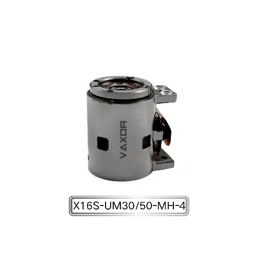
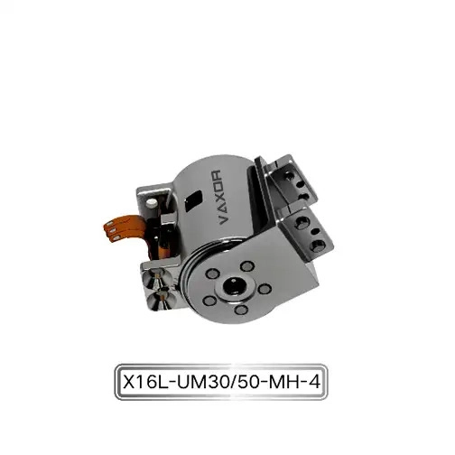
The Φ16mm Micro Joint Actuator is designed for highly integrated robotic systems and dexterous hands. Its compact module format provides a starting point for evaluating how actuation can be incorporated into limited joint spaces. Final suitability still depends on the mechanical loads and motion requirements of the particular hand design.
Match Continuous Torque to Real Operating Loads
Torque is one of the most important specifications when comparing joint actuators, but the meaning of each torque rating must be understood before it is used in a design calculation.
The X16S/L-UM30/50-MH-4 model is specified with continuous torque of up to 200 mNm and initial torque of up to 400 mNm. These figures describe different operating conditions and should not be treated as equivalent.
Continuous torque is relevant when assessing the load that a joint must handle over an extended operating period, subject to the manufacturer's specified conditions. Initial torque describes a different operating point and should not automatically be interpreted as a continuous output capability. Engineers should confirm the exact definition, duration, and test conditions associated with the initial torque specification before using it to size a mechanism.
Consider a finger joint that must maintain a grasp for several seconds or longer. The required torque should be assessed against the continuous operating capability, including the effects of motor temperature, transmission efficiency, and the intended duty cycle. If the finger also needs to accelerate rapidly or overcome a brief increase in resistance, its transient torque requirements should be evaluated separately.
A practical selection process should include three checks:
Estimate the torque needed for the intended grasping and manipulation tasks.
Allow for friction, external disturbances, and variation between operating conditions.
Verify that both sustained and short-duration loads remain within the applicable actuator limits.
Avoid sizing a joint solely around the highest torque figure in a product specification. A more reliable design uses the torque needed during normal operation as its starting point and then evaluates transient demands, safety margins, and thermal constraints.
Choose the Gear Ratio for the Required Motion
The gear ratio influences the relationship between motor rotation and joint output. A higher reduction ratio generally provides greater torque multiplication while reducing output speed, although the actual result depends on the motor characteristics and transmission efficiency.
The Φ16mm Micro Joint Actuator is available with 30:1 and 50:1 gear ratio options. These configurations give engineers an opportunity to match the drive to different joint requirements rather than relying on a single configuration for every finger.
A 30:1 ratio may be worth evaluating when a joint needs a balance between output speed and torque. A 50:1 ratio may be appropriate when the design places greater emphasis on torque multiplication and can accommodate the associated reduction in output speed. These are general engineering considerations, not guaranteed performance differences for every operating condition; the relevant speed-torque data should be confirmed for each configuration.
The choice also depends on how the robotic hand will be used. A finger designed for rapid repositioning may have different priorities from one intended to maintain a firm grip or perform controlled manipulation against resistance.
When comparing the two options, engineers should assess:
Required joint speed and angular travel.
Torque needed at the output shaft.
Acceleration and deceleration requirements.
Transmission efficiency and mechanical backlash, where applicable.
Control response under changing loads.
It is also important to consider the control system. A gear ratio that satisfies the static torque requirement may not deliver the desired movement time or response to commands. Testing both the required output torque and the intended motion profile can help establish which configuration is appropriate.
Consider Position Feedback and Angular Accuracy
Precise finger movement depends on the complete control system, not just the actuator's mechanical structure. Position sensing allows the controller to estimate joint position and adjust its commands according to the measured state.
The X16S/L-UM30/50-MH-4 uses an absolute magnetic encoder and specifies angular accuracy of up to 0.02°. This capability can be relevant to applications requiring controlled joint positioning, particularly when a robotic hand must coordinate several fingers or manipulate objects with limited clearance.
An absolute encoder provides position information referenced to a defined angular position, but the exact behavior depends on the encoder implementation and control architecture. Engineers should verify how position data is initialized, transmitted, and interpreted by the host controller. They should also distinguish encoder resolution from system-level positioning accuracy.
Even when an actuator has a high-precision encoder, the complete mechanism may introduce errors through mechanical compliance, mounting tolerances, backlash, structural deformation, or calibration offsets. The fingertip's actual position also depends on the geometry of the finger links and the combined motion of multiple joints.
For this reason, validation should extend beyond checking encoder readings. A useful prototype test measures joint movement and, where possible, fingertip positioning under representative loads. Repeating these measurements at different positions can reveal mechanical effects that are not apparent when the actuator is tested on its own.
Plan the SPI Communication Interface Early
The actuator's SPI communication interface is another important consideration during integration. Engineers should determine how the actuator will communicate with the main controller and how multiple joints will be managed within the available control cycle.
SPI is a synchronous serial communication interface commonly used for communication between electronic devices. Its implementation requires attention to signal connections, clock configuration, timing, and the electrical characteristics of the connected hardware. The actuator's specific command structure and communication timing should be obtained from its technical documentation rather than assumed from the general SPI standard.
For a multi-joint robotic hand, communication planning should cover more than whether the controller can read position data. The design team should consider the update rate needed for coordinated movement, the time required to process commands, fault detection, and the handling of communication interruptions.
A useful integration checklist includes:
Confirm the controller's electrical compatibility with the actuator interface.
Verify signal connections and communication timing against the product documentation.
Test position-data reading and command execution with one actuator before scaling up.
Measure communication delays under the intended control workload.
Define how the system responds to missing data or communication errors.
These checks can identify integration issues before several actuators are installed inside a tightly packed hand structure. They also help ensure that the communication design supports the intended motion-control strategy.
Account for Weight and Installation Space
A dexterous hand often contains several actuators, structural links, sensors, wiring, and protective components. Even a small difference in the weight or size of each module can influence the final design, particularly when the hand must be mounted on a lightweight robotic arm.
The specified weight of the Φ16mm Micro Joint Actuator is 24.3–26.1 g, depending on configuration. Engineers should use the weight of the selected version when calculating the total mass of the hand rather than relying on a single approximate figure.
Weight matters not only because of the total payload. Actuator placement affects the inertia of moving finger segments. Additional mass farther from a joint axis can increase the torque required for acceleration and alter the response of the mechanism. This can create a feedback loop in the design: a heavier assembly requires more torque, which may influence the choice of actuator configuration and supporting structure.
Mechanical integration should also include mounting clearances, fastener access, wiring paths, connector orientation, and space for assembly and maintenance. A CAD fit check can reveal interference between neighboring modules, finger links, and cables before a physical prototype is produced.
Once the layout is established, a physical mock-up or early prototype can be used to confirm that the actuators can be installed and serviced as planned. This is particularly valuable when several joints must fit within a narrow finger or palm structure.
Validate the Actuator in a Complete Finger Assembly
Specifications are essential for screening candidate actuators, but they cannot fully predict how a joint will perform in the finished hand. A prototype test should therefore evaluate the actuator under conditions that reflect its intended application.
Begin with basic functional checks, including power-up behavior, communication, position feedback, and unloaded motion. Next, introduce representative mechanical loads and evaluate the joint's speed, torque demand, movement consistency, and temperature during the intended operating cycle.
For a dexterous hand, testing should also cover repeated grasping and release. The finger should be evaluated at different joint positions and under different object sizes or resistance levels. These tests can reveal issues related to mechanical interference, load distribution, motion coordination, or controller tuning.
Useful measurements include:
Joint movement time and position response.
Output behavior under representative loads.
Current consumption and temperature during repeated operation.
Repeatability of the intended motion sequence.
Communication reliability during multi-joint operation.
Mechanical wear or looseness observed during endurance testing.
The test plan should reflect the expected duty cycle and environment. If the hand will perform frequent repetitive tasks, a short demonstration is not sufficient to establish long-term reliability. Endurance testing and inspection should be planned according to the project's performance and service-life requirements.
Working with a Micro-Drive Technology Partner
Selecting an actuator for a dexterous hand often involves coordination between mechanical design, motor engineering, embedded control, and manufacturing. A supplier with experience across these areas can help the development team clarify specifications and assess the feasibility of moving from a prototype to repeatable production.
Founded in 2024 and headquartered in Suzhou, China, VAXOR develops micro joint actuators and ultra-micro coreless motors for robotics, medical devices, precision instruments, and intelligent equipment. Its technical approach combines motor design, precision manufacturing, robotics control, structural design, and intelligent manufacturing.
The company also develops compact motion solutions using technologies such as axial-flux motors, PCB/FPCB winding, optimized electromagnetic design, and miniature reduction mechanisms. Its team works across engineering development and production implementation, with a focus on moving high-performance micro-drive technology from prototype validation toward scalable manufacturing.
When evaluating a module for a robotic hand, engineering teams should share the intended application, joint load estimates, target speed, motion range, voltage requirements, control architecture, and installation constraints. They should also confirm which specifications apply to the exact model and gear ratio being considered.
For the Φ16mm Micro Joint Actuator, the combination of a 12 V or 24 V supply option, 30:1 or 50:1 gear ratios, an absolute magnetic encoder, and SPI communication provides several key parameters for this evaluation. The final decision should be based on verified technical documentation and prototype testing under the intended operating conditions.
Final Checklist for Selecting a Finger-Joint Actuator
Before finalizing an actuator for a dexterous hand, verify the following points:
Mechanical load: Estimate the required torque, including friction, acceleration, and external forces.
Torque rating: Distinguish continuous torque from initial torque and confirm their specified operating conditions.
Gear ratio: Compare the required output speed and torque for the 30:1 and 50:1 options.
Position feedback: Confirm encoder behavior, accuracy specifications, calibration requirements, and controller compatibility.
Communication: Validate SPI electrical connections, timing, and data handling.
Size and weight: Check module clearance, total hand mass, cable routing, and assembly access.
Thermal and endurance performance: Test the actuator during representative repetitive tasks.
Production readiness: Confirm documentation, configuration details, and validation requirements before scaling the design.
Choosing a suitable micro joint actuator is a system-level engineering decision. Torque, gear ratio, feedback, communication, weight, and mechanical layout must work together to deliver the required finger movement. By evaluating these factors before final integration, developers can reduce avoidable redesigns and build a stronger technical foundation for reliable dexterous robotic hands.
The Φ16mm Micro Joint Actuator offers a compact motion module with defined torque, gear ratio, encoder, and communication options for this evaluation. Working with VAXOR and validating the selected configuration against real application loads can help engineering teams determine whether the module meets their robotic hand's requirements.