 Store

 EN
 CN
 VI
 IT
 ES
 TH
 JA
 PT
 MS
 KO
 FR
 DE
 ID
As robotic systems become more compact, their joint actuators are expected to deliver higher output torque without requiring significantly more installation space. This creates an important engineering challenge: the motor and transmission must operate within a limited volume while managing the heat generated during movement and load holding.
Thermal design is particularly important in collaborative robots and biomimetic robotic joints, where actuators may perform repeated movements, maintain positions under load, and operate in relatively enclosed mechanical structures. Even when an actuator meets the required torque specification, inadequate heat management can affect its operating stability, service life, and long-term reliability.
For engineers selecting a Φ25mm Micro Joint Actuator, thermal performance should therefore be considered alongside torque, weight, transmission configuration, and control requirements. Understanding where heat comes from and how it moves through the complete joint assembly helps designers establish more realistic operating conditions and avoid unnecessary thermal stress.
Why Thermal Management Matters in High-Torque Robotic Joints
An electric actuator converts electrical energy into mechanical motion, but not all input energy becomes useful output power. Some energy is dissipated as heat through electrical resistance, magnetic losses, mechanical friction, and other operating losses.
In a robotic joint, heat generation can vary significantly depending on the movement being performed. A joint accelerating a load, maintaining a fixed position, or repeatedly changing direction may experience different electrical and mechanical demands.
Several factors make thermal management especially important in compact, high-torque actuators.
First, the available space for heat dissipation is limited. A small actuator has less external surface area than a larger motor assembly, and its surrounding mechanical structure may restrict airflow or direct heat transfer.
Second, high torque requirements can increase the electrical and mechanical demands placed on the drive system. The actual heat generated depends on motor characteristics, current, operating speed, transmission efficiency, and control strategy rather than torque alone.
Third, robotic joints often operate in repeated motion cycles. A single short movement may not cause a significant temperature increase, but frequent operation with insufficient cooling intervals can lead to accumulated heat.
For these reasons, thermal performance should be evaluated under realistic operating conditions rather than inferred from a single torque rating.
Main Sources of Heat in a Robotic Joint Actuator
Understanding the main heat sources is the first step toward developing an effective thermal design.
Motor winding losses
Electrical resistance in motor windings generates heat when current flows through the conductors. These losses are commonly referred to as copper losses and increase with current.
In simplified terms, winding losses can be expressed as:
[P_{\mathrm{Cu}}=I^2R]
Where (I) represents the winding current and (R) represents winding resistance.
This relationship explains why high-current operating conditions require particular attention. An increase in current can produce a disproportionate increase in resistive heating.
The actual winding temperature also depends on how effectively heat is transferred away from the motor and how much time the actuator spends under load.
Magnetic and electromagnetic losses
Motor operation also produces losses associated with changing magnetic fields and the electromagnetic characteristics of the motor. These may include core losses and other electromagnetic losses, depending on the motor construction and operating conditions.
An axial-flux motor architecture can provide a compact approach to generating torque, but its thermal behavior still needs to be assessed according to its specific electromagnetic design, materials, winding configuration, and operating speed.
A compact motor should not automatically be assumed to have better thermal performance simply because it has a high torque density.
Mechanical transmission losses
The reduction mechanism also contributes to heat generation. Friction between mechanical components, bearing losses, lubrication conditions, and transmission loading can all influence the amount of energy dissipated during operation.
In an integrated joint actuator, heat from the motor and transmission may accumulate within the same housing. Thermal design should therefore consider the complete drive module instead of evaluating the motor in isolation.
How Continuous Torque Affects Thermal Design
Continuous torque is one of the most important specifications when evaluating the thermal requirements of a robotic joint.
Unlike a short-duration torque demand, continuous torque relates to sustained operating capability under the manufacturer's specified conditions. When an actuator repeatedly supports a load or maintains a joint position, the motor may experience prolonged current flow and continuous heat generation.
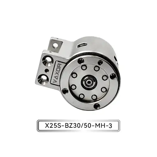
The Φ25mm Micro Joint Actuator offers continuous torque of up to 1150 mNm and initial torque of up to 1800 mNm. These two specifications describe different operating conditions and should be considered separately during thermal evaluation.
The continuous torque rating is particularly relevant when determining whether an actuator can support the normal workload of a robot over an extended period.
The initial torque rating should not automatically be treated as a continuous or peak operating limit. Its applicable duration, current requirements, and test conditions need to be confirmed with the manufacturer before it is used to define a thermal operating envelope.
For system designers, several questions should be addressed:
How long does the joint operate under sustained load?
How frequently does the actuator accelerate or decelerate?
Does the joint need to hold a load while the motor remains energized?
How much time is available between operating cycles?
Does the actuator operate inside an enclosed structure?
What are the ambient temperature and cooling conditions?
These factors help establish whether the selected actuator can maintain its required performance without exceeding its thermal limits.
Thermal Design Challenges in Compact Actuator Structures
Compact robotic joints often combine the motor, reduction mechanism, encoder, and associated electrical components within a limited installation space. This integration reduces the space required by the overall robot, but it also creates thermal design constraints.
Limited heat dissipation area
A smaller external surface area can restrict the amount of heat transferred from the actuator to its surroundings. If the actuator is installed inside a tightly enclosed joint housing, natural convection may also be limited.
Designers should examine whether the surrounding structure can provide an effective path for heat transfer. The mounting interface, housing materials, contact surfaces, and nearby components may all influence the thermal behavior of the assembly.
Heat transfer between integrated components
When the motor and reduction mechanism are installed close together, heat generated in one component may affect the temperature of another.
For example, heat from the motor can be transferred through the housing or mechanical connections to nearby transmission components. The resulting temperature distribution depends on the materials, geometry, contact resistance, and operating conditions.
This is particularly relevant when the joint module is installed inside a robotic arm with limited ventilation.
Thermal effects on nearby electronics
Encoders, communication circuits, and other electronic components also have operating temperature requirements. Even if the motor itself remains within its permitted temperature range, heat accumulation around the control electronics may affect system reliability.
A complete thermal assessment should therefore consider the temperature conditions of all integrated components, not only the motor winding.
Practical Thermal Design Measures for Robotic Joint Systems
Thermal management does not always require a separate cooling system. In many compact robotic applications, improvements to the mechanical layout and operating strategy can help manage heat more effectively.
1. Establish a realistic load profile
Start by identifying the actual movement sequence of the robot. Record the expected load, joint position, acceleration, operating duration, and rest intervals.
A joint that performs occasional high-load movements may have different thermal requirements from one that operates continuously at a moderate load. The duty cycle should reflect the real application rather than an idealized test sequence.
2. Improve the heat transfer path
The actuator mounting structure can influence how heat moves away from the drive module. Designers should evaluate the thermal conductivity of adjacent materials, the quality of mechanical contact, and whether the housing provides a useful path for heat dissipation.
Where appropriate, the robot's structural components can be considered as part of the overall thermal design.
3. Avoid unnecessary current demand
The control system should be configured according to the actual torque requirements of the joint. Excessive current demand can increase winding losses and create additional thermal stress.
Appropriate motion profiles, acceleration settings, and current limits can help prevent the actuator from operating under unnecessarily demanding conditions.
4. Evaluate holding strategies
Some robotic joints need to maintain a position for extended periods. Depending on the motor and control design, holding a load may continue to generate electrical losses.
Engineers should evaluate whether the application requires continuous energized holding or whether the mechanical design and control strategy can reduce the time spent in high-current holding conditions.
5. Verify the design through testing
Thermal calculations provide useful guidance, but testing is necessary to confirm performance in the actual assembly.
Temperature measurements should be taken under representative operating conditions, including repeated motion cycles, sustained loading, and the expected ambient environment. Where direct measurement of internal components is not practical, appropriate test methods and manufacturer data should be used to assess internal thermal conditions.
Evaluating the Φ25mm Micro Joint Actuator in Thermal Applications
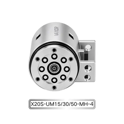
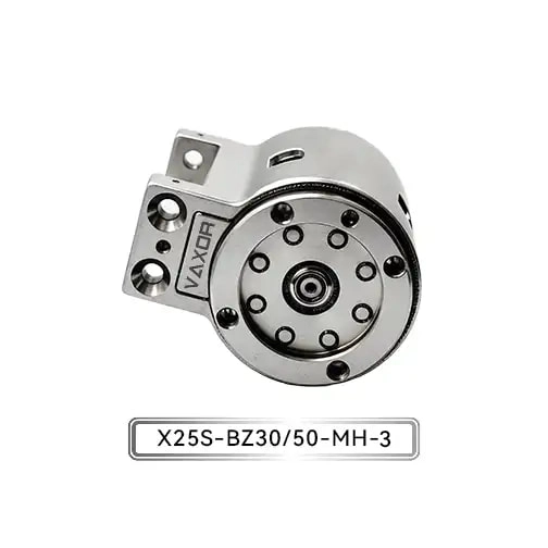
The Φ25mm Micro Joint Actuator integrates an axial-flux motor, a miniature cycloidal reducer, and a non-contact encoder. This configuration is intended to balance precision, load capacity, and cost for applications such as collaborative robots and biomimetic joints.
Its published specifications include:
| Parameter | Specification |
|---|---|
| Model | X25S-UZ/BZ30/50-MH-3 |
| Voltage | 12–18 V |
| Gear Ratio | 30 / 50 |
| Continuous Torque | Up to 1150 mNm |
| Initial Torque | Up to 1800 mNm |
| Encoder | Absolute Magnetic Encoder |
| Communication | CAN FD |
| Weight | 93–103 g |
For thermal design, the continuous torque specification provides a useful reference for evaluating sustained mechanical requirements. However, the actual operating temperature will also depend on current, speed, load profile, installation, and cooling conditions.
The 30:1 and 50:1 reduction configurations should be evaluated according to the application's output speed and torque requirements. Different transmission configurations can change the motor's operating point and the distribution of mechanical losses, so thermal behavior should be verified for the selected version.
The absolute magnetic encoder provides position feedback, while CAN FD supports communication with a compatible robotic control system. These features contribute to system integration, but they do not replace the need for thermal monitoring and operating-limit verification.
Thermal Validation Before Mass Production
For manufacturers developing robotic joints, thermal validation should be included early in the engineering process.
A useful validation procedure begins with defining the expected load and motion profile. The actuator can then be tested under representative operating conditions while monitoring relevant temperatures and checking whether its performance remains stable.
Testing should consider continuous operation, repeated acceleration, load holding, and realistic cooling intervals. The complete joint assembly should also be evaluated because its mounting structure and enclosure may affect heat dissipation.
For applications involving multiple actuators, testing should reflect the combined operating conditions of the robot. Several joints moving simultaneously may create different power and thermal demands from testing each actuator independently.
The results can be used to refine the control strategy, mechanical installation, and operating limits before the design moves into pilot production or batch manufacturing.
Developing Compact Drive Solutions with VAXOR
Founded in 2024 and headquartered in Suzhou, China, VAXOR develops micro joint actuators and ultra-micro coreless motors for robotics, medical devices, precision instruments, and intelligent equipment.
Its multidisciplinary team combines expertise in motor design, precision manufacturing, structural design, robotics control, and intelligent manufacturing. The company focuses on engineering implementation, with experience covering prototype validation, pilot production, and batch delivery.
VAXOR's technology roadmap includes axial-flux motors, PCB/FPCB winding, optimized electromagnetic design, and miniature reduction mechanisms. These technologies support its development of compact drive solutions with high torque density, fast response, and consistent manufacturing performance.
For high-torque robotic joints, thermal design must be considered alongside torque output, mechanical integration, and control requirements. By evaluating the complete operating cycle and validating the assembled system under realistic conditions, engineers can make more informed decisions about actuator selection and long-term operation.
The Φ25mm Micro Joint Actuator provides a compact drive option for collaborative robots and biomimetic joints. Its continuous torque capability, integrated transmission, and position feedback make it relevant to applications where load capacity and installation space must be balanced. Ultimately, effective thermal management depends not only on the actuator itself, but also on how the motor, transmission, control system, and robot structure work together.