 Store
Store
 EN
EN CN
CN VI
VI IT
IT ES
ES TH
TH JA
JA PT
PT MS
MS KO
KO FR
FR DE
DE ID
IDChoosing a gear ratio for a robotic joint is not simply a matter of maximizing output torque. The ratio also affects joint speed, acceleration, responsiveness, and how the actuator interacts with the mechanical load. A ratio that works well for a slow, force-oriented mechanism may not be suitable for a joint that needs rapid repositioning or frequent changes in direction.
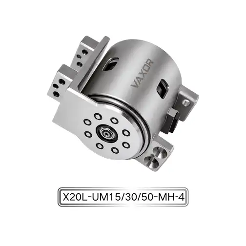
For engineers developing compact robotic arms, dexterous hands, and automated mechanisms, selecting the right configuration early can simplify motion-control development and reduce the need for mechanical redesign. The Φ20mm Micro Joint Actuator offers 15:1, 30:1, and 50:1 gear ratio options, allowing engineers to evaluate different combinations of output speed and torque within a compact joint module.
The most suitable ratio depends on the actual application requirements, including the required movement time, external load, duty cycle, available power supply, and control strategy. Understanding these factors helps turn the ratio selection process into a practical engineering decision rather than a comparison of numbers alone.
How Gear Ratio Affects Joint Output
A gear ratio describes the relationship between the rotational speed of the motor and the output of the transmission. In a reduction drive, the motor rotates faster than the output shaft. The reduction helps convert the motor's rotational characteristics into a more suitable combination of speed and torque for the driven mechanism.
In general, a higher reduction ratio provides greater torque multiplication while reducing output speed. A lower ratio allows the output to rotate faster for a given motor speed but provides less torque multiplication. Actual output torque and speed also depend on motor performance, transmission efficiency, friction, and operating conditions.
For a micro joint actuator, these differences can affect how a robotic mechanism starts moving, accelerates, maintains its position, and responds to changing loads.
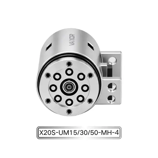
The Φ20mm Micro Joint Actuator, model X20S/L-UM15/30/50-MH-4, is available with three reduction ratios: 15:1, 30:1, and 50:1. Instead of assuming that one ratio is suitable for every application, engineers should compare each configuration against the intended joint motion and load profile.
For example, a joint that needs to move quickly between positions may prioritize output speed and acceleration. A joint that must support a heavier load may place greater emphasis on torque capacity. A mechanism that combines both requirements may need a compromise between speed, torque, and control response.
The objective is to select a ratio that meets the complete operating requirement, not simply the highest available reduction.
When a 15:1 Gear Ratio Makes Sense
A 15:1 ratio is worth evaluating when output speed and rapid movement are important design priorities. Because the reduction is lower than the 30:1 and 50:1 alternatives, it generally permits a higher output speed for a given motor speed.
This can be useful in robotic joints that perform frequent repositioning, move through relatively large angular ranges, or need to complete motion sequences within a limited time.
Potential applications include lightweight robotic mechanisms, fast-moving articulated components, and joints that operate with comparatively modest external loads. However, the final choice should depend on the actuator's actual speed-torque performance rather than the gear ratio alone.
When assessing the 15:1 configuration, engineers should check several factors:
Whether the output speed meets the required movement time.
Whether available torque is sufficient during acceleration and steady operation.
Whether the mechanism can tolerate changes in load without excessive speed variation.
Whether the controller can achieve the required motion profile.
Whether the selected configuration remains within its operating limits during repeated movements.
A lower ratio does not automatically guarantee faster real-world motion. If the load is too demanding, the motor may not accelerate the joint as expected. External friction, inertia, and transmission losses can also limit performance.
For this reason, the 15:1 option should be tested under the actual load and movement profile before it is finalized for a production design.
Why a 30:1 Ratio Can Be a Useful Middle Ground
A 30:1 ratio provides an intermediate option between the lower 15:1 reduction and the higher 50:1 reduction. It may be worth considering when an application needs a balance between output speed and torque multiplication.
Many robotic mechanisms combine different types of movement. A joint may need to reposition quickly when unloaded but also provide sufficient torque when interacting with an object. Selecting an intermediate ratio can be one way to evaluate this trade-off.
For instance, an articulated mechanism may need to move between programmed positions while maintaining predictable performance as its external load changes. In this case, engineers should compare the expected speed under load, acceleration time, and required output torque rather than relying only on the nominal gear ratio.
The 30:1 configuration can be evaluated against the following questions:
Does the joint reach its target position within the required time?
Is the available torque sufficient for the intended working load?
Can the actuator respond appropriately when the load changes?
Does the configuration support the required frequency of repeated movement?
Is the motion profile achievable without exceeding the actuator's operating limits?
These questions help determine whether the intermediate ratio provides the desired balance for the application. The answer should be based on measured or manufacturer-supplied performance data for the selected configuration.
When to Consider a 50:1 Gear Ratio
A 50:1 ratio is worth evaluating when torque multiplication is a higher priority than maximum output speed. Compared with lower reduction ratios, a higher reduction generally reduces output speed while increasing the torque available at the output for a given motor torque, subject to transmission efficiency and operating limits.
This can be relevant to joints that move against greater resistance, handle demanding mechanical loads, or require controlled movement at comparatively low output speeds.
However, higher reduction is not automatically the best choice for a force-oriented application. The designer must also consider acceleration, reversal behavior, transmission characteristics, and the required response to control commands.
A high ratio may limit output speed for applications that need rapid movement. It may also affect how the system behaves during frequent direction changes. The relevant performance characteristics should therefore be evaluated using the actuator's technical data and representative testing.
For the Φ20mm Micro Joint Actuator, the 50:1 option can be compared with the other ratios using the same load and motion requirements. This makes it possible to determine whether the additional reduction provides a meaningful benefit for the intended mechanism.
The comparison should focus on actual output speed, torque under load, response time, and thermal behavior during the required duty cycle.
Compare the Ratios Using the Same Operating Requirements
The most reliable way to select a gear ratio is to compare all available configurations against a consistent set of requirements. Comparing one ratio under a light load with another under a heavier load can produce misleading conclusions.
Start by defining the required output speed and torque. Then estimate the inertia of the driven components, the required acceleration time, and the frequency of repeated movements. These values provide a practical basis for evaluating the different configurations.
The following table summarizes the general trade-offs to investigate.
| Selection factor | 15:1 | 30:1 | 50:1 |
|---|---|---|---|
| General reduction level | Lower | Intermediate | Higher |
| Output speed potential | Generally higher | Intermediate | Generally lower |
| Torque multiplication | Generally lower | Intermediate | Generally higher |
| Main evaluation priority | Speed and acceleration | Balance of speed and torque | Torque requirements and lower-speed operation |
| Key validation | Loaded speed and acceleration | Overall motion profile | Torque, response, and operating limits |
These are general characteristics of reduction ratios, not measured performance rankings for this specific actuator. Actual output values depend on the motor, transmission efficiency, controller, and operating conditions.
Engineers should request the relevant speed-torque curves and configuration-specific performance data before making a final selection.
Consider Continuous Torque and Initial Torque
Gear ratio selection must also account for the type of load the joint will experience. A mechanism that briefly encounters a high resistance may have different requirements from one that maintains a load throughout a long operating cycle.
The X20 actuator series specifies continuous torque of up to 450 mNm and initial torque of up to 800 mNm. These are maximum stated values and should not be assumed to apply identically to every gear ratio or operating condition without confirmation from the relevant technical documentation.
Continuous torque is important when estimating performance under sustained operating loads. Initial torque refers to a different operating condition, and its precise definition and permissible duration should be confirmed with the manufacturer.
For practical selection, engineers should separate the load into at least three categories:
Steady-state load: The torque required during normal operation.
Acceleration load: The additional torque needed to change the speed of the moving components.
Transient load: Short-duration increases in resistance during specific tasks.
The actuator must meet the application's actual requirements across these conditions. It is not sufficient to select a ratio based on a maximum torque figure if the mechanism cannot maintain the required speed or operate within its thermal limits.
The selected ratio should therefore be validated using a representative movement sequence rather than a single static load measurement.
Account for Voltage and Control Requirements
The X20 actuator series supports 12 V, 24 V, and 48 V supply options. These options can be relevant when integrating the joint into robotic systems with different power architectures, but the available voltage must be confirmed for the specific model and configuration being purchased.
The power supply, motor driver, and control system should be evaluated together. Engineers should verify electrical compatibility, current capacity, protection requirements, and the controller's ability to deliver the required motion profile.
The actuator also features an absolute magnetic encoder and SPI communication. The encoder provides position feedback, while the SPI interface supports communication with a compatible control system. The exact communication timing, command structure, and position-data format should be confirmed from the manufacturer's documentation.
Gear ratio and feedback control should not be treated as independent decisions. The chosen ratio affects the relationship between motor movement and joint output, while the control system determines how the actuator follows position and motion commands.
During prototype testing, measure output movement time, position response, current consumption, and performance under representative loads. If several joints operate together, test the communication and power system under the expected combined workload.
Evaluate Space, Weight, and Mechanical Integration
The X20 module measures Φ20mm × 20mm and has a specified weight range of 37.2–41.6 g, depending on configuration. These characteristics make installation planning an important part of the selection process.
Before choosing a ratio, engineers should confirm that the module fits the available space and that its mounting arrangement is compatible with the surrounding structure. The design should also provide sufficient clearance for connectors, wiring, fasteners, and maintenance access.
Weight can affect the inertia of the overall mechanism, especially when an actuator is installed on a moving arm or near the end of a robotic structure. Additional mass may increase the torque needed to accelerate upstream joints, so the actuator should be evaluated as part of the complete mechanical system.
The Φ20mm Micro Joint Actuator uses an axial-flux motor architecture. VAXOR states that this architecture delivers over 30% higher torque density than conventional designs. When assessing this claim for a specific application, engineers should confirm the relevant comparison basis and determine how the module's performance fits the complete system's space, mass, and load requirements.
A CAD layout review followed by physical prototype testing can help identify mechanical interference, alignment issues, and unexpected loads before the design moves toward production.
Validate the Selected Ratio Through Prototype Testing
Calculations can narrow the choices, but testing is needed to establish whether the selected configuration meets the actual application requirements.
Begin with the intended supply voltage, controller, mounting structure, and mechanical load. Record the output speed, movement time, current consumption, and temperature during representative operating cycles.
Next, test acceleration, deceleration, repeated direction changes, and changes in external load. For robotic mechanisms, it is also useful to evaluate how the actuator performs during the complete motion sequence rather than testing each movement in isolation.
A practical validation process should include:
Confirming that the module and controller are compatible.
Measuring loaded output speed and movement time.
Checking torque requirements during acceleration and steady operation.
Monitoring current and temperature throughout the duty cycle.
Evaluating position feedback and response to control commands.
Repeating the test to check consistency under comparable conditions.
If more than one gear ratio appears suitable, test the alternatives using the same mechanical load and movement profile. This provides a fair basis for comparison and helps identify the configuration that best satisfies the project's requirements.
Working with a Micro-Drive Technology Partner
Selecting the right ratio often requires coordination between mechanical engineering, motor design, and control development. A micro-drive technology partner can help clarify configuration differences and identify the technical data needed for a reliable decision.
Founded in 2024 and headquartered in Suzhou, China, VAXOR develops micro joint actuators and ultra-micro coreless motors for robotics, medical devices, precision instruments, and intelligent equipment. Its engineering capabilities cover motor design, precision manufacturing, structural design, robotics control, and intelligent manufacturing.
The company's technology roadmap includes axial-flux motor technology, PCB/FPCB winding, electromagnetic design, and miniature reduction mechanisms. VAXOR also focuses on engineering implementation from prototype validation and pilot production toward batch delivery.
When discussing a project, provide the required output speed, continuous and transient torque requirements, load inertia, movement cycle, supply voltage, control interface, and installation constraints. These details allow the supplier to help identify the relevant configuration and clarify which performance data must be verified.
The Φ20mm Micro Joint Actuator, model X20S/L-UM15/30/50-MH-4, provides three gear ratio options, multiple voltage options, an absolute magnetic encoder, and SPI communication. By comparing the ratios against the actual load and validating the selected module in a prototype, engineers can make a more informed decision for their robotic joint design.
Final Selection Checklist
Before finalizing a gear ratio, confirm the following:
Required output speed: Determine how quickly the joint must complete its movement.
Torque demand: Separate steady-state, acceleration, and transient loads.
Gear ratio: Compare 15:1, 30:1, and 50:1 using the same operating requirements.
Power supply: Confirm the available voltage and compatibility with the selected configuration.
Feedback and communication: Verify encoder integration and SPI communication requirements.
Mechanical layout: Check mounting space, weight, wiring, and surrounding components.
Operating cycle: Evaluate repeated movement, current consumption, and temperature.
Performance data: Confirm configuration-specific specifications before final approval.
There is no universally correct gear ratio for every robotic joint. The best choice is the one that satisfies the application's speed, torque, control, and operating requirements without creating unnecessary compromises elsewhere in the system.
By comparing the 15:1, 30:1, and 50:1 options through a consistent engineering process, developers can select a configuration based on actual performance needs. The Φ20mm Micro Joint Actuator offers a useful platform for this evaluation, while collaboration with VAXOR can help clarify specifications and support the path from prototype testing to production integration.