 Store
Store
 EN
EN CN
CN VI
VI IT
IT ES
ES TH
TH JA
JA PT
PT MS
MS KO
KO FR
FR DE
DE ID
IDDesigning compact medical devices often involves a difficult trade-off between available space and required mechanical performance. A handheld diagnostic instrument, miniature sampling mechanism, or compact fluid-control device may need a small motor to drive a moving component without increasing the overall size or weight of the equipment. In these applications, even a few millimeters of additional space can affect the enclosure, internal layout, battery capacity, and ease of assembly.
Motor selection therefore needs to go beyond external dimensions. Engineers must consider operating speed, available torque, power supply, thermal behavior, and the load imposed by the driven mechanism. A motor that fits inside the housing but cannot maintain the required speed under load will not solve the design problem.
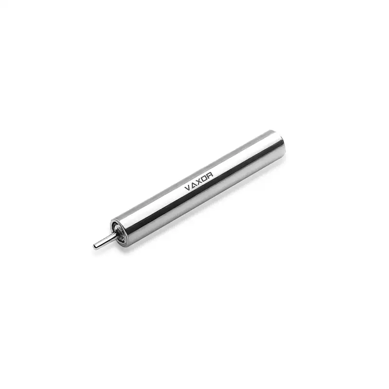
The φ4mm Ultra-micro Brushless Coreless Motor is designed for applications where installation space is extremely limited. With a diameter of just 4 mm, it provides a potential drive option for compact medical devices, precision instruments, and other miniature equipment. To determine whether this type of motor fits a specific design, engineers should start with the mechanism's actual operating requirements and evaluate the motor's performance under realistic conditions.
Define the Mechanical Requirements Before Choosing a Motor
The first step is to identify what the motor needs to move. Medical devices contain a wide range of mechanisms, including small rotating components, positioning assemblies, miniature pumps, and precision adjustment systems. Each creates a different combination of speed, torque, and operating-cycle requirements.
For example, a miniature positioning mechanism may require controlled movement over a limited angle, while a rotating assembly may need to maintain a relatively stable speed throughout a working cycle. A mechanism that starts and stops frequently may also have different requirements from one that runs continuously.
Before comparing motor specifications, document the following parameters:
The required output speed under the intended mechanical load.
The torque needed to overcome friction and move the mechanism.
The expected operating duration and frequency of start-stop cycles.
The available installation diameter, length, and mounting space.
The permitted supply voltage and current consumption.
The acceptable temperature rise and noise level for the complete device.
These requirements help engineers establish a realistic operating point instead of selecting a motor based solely on its highest advertised speed.
It is also important to distinguish between the motor's shaft output and the performance of the complete mechanism. Bearings, couplings, gears, seals, and other transmission components can introduce friction and losses. If the application uses a reduction mechanism, the resulting output speed and torque must be evaluated at the driven component rather than inferred directly from the motor's shaft specifications.
Why a 4mm Motor Can Matter in Medical Device Design
Reducing motor diameter can make it easier to integrate a drive into a narrow housing or a densely packed assembly. This is particularly relevant when a medical device must accommodate sensors, electronic control boards, connectors, batteries, and mechanical components within the same enclosure.
A smaller motor can also give designers more flexibility when arranging components around a moving mechanism. However, reducing the motor's size does not automatically improve the performance of the complete device. The motor still needs to meet the application's load and speed requirements, and its mounting arrangement must provide sufficient mechanical support.
The φ4mm Ultra-micro Brushless Coreless Motor, model G04P-VW00-QZ-1, has a specified weight of 1.7 g and a rated supply voltage of 6 V. These characteristics make it relevant for preliminary evaluation in weight- and space-constrained designs.
During mechanical integration, engineers should consider the motor's full envelope, including its length, shaft dimensions, mounting requirements, and clearance around connected components. The diameter alone is not sufficient to confirm that the motor will fit a particular assembly.
Designers should also evaluate how the motor is supported. An extremely small motor may require a carefully designed holder or mounting interface to prevent unwanted movement and avoid transferring excessive mechanical stress to the housing or shaft.
Match Operating Speed to the Actual Workload
Speed is often one of the first specifications engineers compare when selecting a miniature motor. However, no-load speed and nominal speed describe different operating conditions.
The no-load speed is measured when the motor runs without an external mechanical load on its shaft. Once the motor drives a mechanism, the operating point changes because torque is required to overcome the load and internal losses.
The nominal speed represents a specified operating condition under the manufacturer's rating method. It is generally more useful than no-load speed when estimating performance in a working device, although the exact test conditions should still be confirmed.
For the G04P-VW00-QZ-1, the specified no-load speed is 55,000 rpm, while the nominal speed is 30,000 rpm. This distinction matters when a medical device requires repeatable motion under load.
Suppose a miniature mechanism needs to rotate at a defined speed during normal operation. Engineers should first determine whether the required speed is compatible with the motor's nominal operating range. They should then account for any speed reduction introduced by the transmission and any variation caused by changes in load.
If a gearbox or other reduction mechanism is used, the output speed will depend on the reduction ratio and transmission losses. A high motor speed may therefore be useful even when the driven component itself operates much more slowly.
The key is to select the motor based on the speed required at the application level, not simply the highest number in the specification sheet.
Evaluate Torque Before Finalizing the Selection
A motor's ability to reach a target speed does not establish whether it can move the intended load. Torque must be evaluated alongside speed because the mechanical output depends on both.
The φ4mm motor has a specified nominal torque of 0.38 mN·m and a stalling torque of 0.76 mN·m. These values should be interpreted according to the manufacturer's rating conditions.
Nominal torque is the more relevant starting point for evaluating normal operation. Stalling torque describes the torque associated with a stationary rotor under the specified test conditions; it should not be treated as a continuous operating capability.
In practical terms, the motor must overcome the combined resistance of the driven mechanism, including friction, mechanical contact, and any load imposed by the application. If the mechanism requires more torque than the motor can deliver at the desired operating point, the design may experience slow movement, failure to start, or excessive current demand.
Engineers can begin by estimating the torque required by the mechanism and comparing it with the motor's operating data. They should also consider starting conditions, because friction and mechanical resistance may be different when the system is stationary.
Where the required torque exceeds the motor's available capability, possible adjustments include reducing friction, changing the mechanism geometry, lowering the required acceleration, or introducing a suitable transmission. Any such change should be assessed against the available space and the effect on the complete device.
Check Electrical Compatibility and Current Demand
A miniature motor must work within the electrical limits of the equipment that powers and controls it. Voltage compatibility is only the first check; engineers also need to estimate current demand and verify that the driver and power supply can support the intended operating conditions.
The G04P-VW00-QZ-1 operates at a specified voltage of 6 V and has a torque constant of 0.82 mN·m/A. The torque constant describes the relationship between motor current and electromagnetic torque under the applicable convention and operating conditions.
As a simplified estimate, the current associated with a required electromagnetic torque can be calculated by dividing that torque by the torque constant. For example, a theoretical torque of 0.20 mN·m corresponds to approximately 0.24 A using the stated torque constant.
This calculation is a starting point, not a complete prediction of the motor's current consumption. Actual performance also depends on winding resistance, electrical losses, rotational speed, the driver, and the mechanical load. Engineers should use the manufacturer's performance curves and electrical data to confirm the expected operating point.
The driver should also be evaluated for startup behavior and stalled-rotor conditions. When the motor cannot rotate as commanded, current and heat generation may become significant. Appropriate current limiting and fault handling can help protect the motor and surrounding electronics.
For battery-powered medical equipment, the electrical assessment should include the expected operating cycle, not just the nominal voltage. Repeated starts, changes in load, and extended operation can all influence energy consumption and battery requirements.
Consider Thermal Behavior in a Small Enclosure
Heat management can become a significant design issue when a motor is installed inside a compact enclosure. Small devices often have limited surface area for heat dissipation, while nearby sensors, batteries, adhesives, and electronic components may have their own temperature constraints.
The amount of heat generated depends on factors such as current, winding resistance, operating speed, mechanical loading, and duty cycle. Consequently, a motor that performs well during a short test may behave differently during repeated or extended operation.
Thermal validation should reflect the intended application. Engineers can test the motor inside a representative enclosure, using the expected load and operating cycle, and monitor temperature over time. The evaluation should include the effects of mounting materials and nearby components because the assembled device may dissipate heat differently from an exposed motor.
If the temperature rises beyond the design limits, the team may need to reduce the duty cycle, adjust the operating point, improve the thermal path, or reconsider the mechanical load.
For medical device development, temperature limits must be established according to the requirements of the complete product and its intended use. The motor's compact size alone does not demonstrate that the finished device meets any particular safety or regulatory requirement.
Account for Noise, Vibration, and Mechanical Integration
Medical devices and precision instruments may require smooth, predictable motion. Depending on the application, unwanted noise or vibration can affect user experience, measurement stability, or the behavior of nearby components.
These characteristics should be assessed at the assembly level. Motor mounting, shaft alignment, bearing support, coupling design, and the balance of rotating components can all influence the final result.
A well-designed mounting interface helps maintain alignment and reduces the risk of unwanted movement. The driven mechanism should also be checked for friction, backlash, and mechanical resonance where relevant.
When the motor is used in a precision positioning system, engineers should distinguish between motor speed stability and the positioning performance of the complete mechanism. A motor specification does not independently establish system-level positioning accuracy.
The φ4mm Ultra-micro Brushless Coreless Motor can be evaluated as part of such a system, with its performance assessed alongside the driver, transmission, mounting structure, and control strategy.
For development teams, prototype testing is the practical way to identify integration issues before committing to the final housing and production design.
Validate the Motor in a Representative Prototype
A specification sheet helps narrow the available options, but the final decision should be based on testing under conditions that represent the intended use.
A useful validation plan should cover several areas:
Speed under load: Confirm that the mechanism reaches and maintains the required operating speed.
Torque capability: Verify that the motor starts and operates reliably against the expected mechanical resistance.
Current consumption: Measure current during startup, normal operation, and demanding load conditions.
Thermal performance: Monitor temperature during representative operating cycles.
Mechanical behavior: Check vibration, shaft alignment, mounting stability, and coupling performance.
Reliability: Test repeated starts, stops, and operating cycles appropriate to the product's development stage.
Where the device has strict size constraints, testing should use a representative enclosure rather than an open bench setup. This helps reveal packaging, wiring, thermal, and mechanical problems that may not appear during initial motor testing.
The validation plan should also reflect the device's intended operating environment and applicable product requirements. Medical applications may require additional system-level safety, reliability, and regulatory assessments that cannot be established from motor specifications alone.
Working With a Micro-Drive Technology Partner
Choosing an ultra-micro motor often involves coordination between mechanical design, electrical engineering, manufacturing, and system integration. Early technical discussions can help clarify dimensional requirements, load conditions, operating cycles, and the data needed to confirm suitability.
Founded in 2024 and headquartered in Suzhou, China, VAXOR develops micro joint actuators and ultra-micro coreless motors for robotics, medical devices, precision instruments, and intelligent equipment. Its technical approach combines motor design, precision manufacturing, structural engineering, and control expertise.
VAXOR's development work includes axial-flux motor technology, PCB/FPCB winding, optimized electromagnetic design, and miniature reduction mechanisms. The company also emphasizes engineering implementation, from prototype validation and pilot production to batch delivery.
For equipment developers, the most useful starting point is to provide a clear set of application requirements, including the available space, operating voltage, target speed, required torque, duty cycle, and thermal constraints. These details make it easier to assess whether a particular motor configuration is suitable and what additional testing may be needed.
Conclusion
Selecting a motor for a compact medical device requires a balance between size, speed, torque, electrical demand, thermal behavior, and mechanical integration. A motor that fits the available space must also deliver the required performance under the actual operating load.
The φ4mm Ultra-micro Brushless Coreless Motor, model G04P-VW00-QZ-1, offers a 4 mm diameter, 6 V operating voltage, 55,000 rpm no-load speed, 30,000 rpm nominal speed, 0.38 mN·m nominal torque, and 1.7 g weight. These specifications provide a useful starting point for evaluating the motor in space-constrained medical devices and precision instruments.
By defining the operating requirements early, checking the motor's speed and torque under load, and validating electrical, thermal, and mechanical performance in a representative prototype, engineers can make a more informed selection. VAXOR provides ultra-micro motor and micro-drive solutions for development teams working on compact equipment where every millimeter of space matters.