 Store
Store
 EN
EN CN
CN VI
VI IT
IT ES
ES TH
TH JA
JA PT
PT MS
MS KO
KO FR
FR DE
DE ID
IDThe elbow joint of a humanoid robot must do more than lift an object. It needs to support the weight of the forearm, maintain control when the arm extends, accelerate smoothly during movement, and respond consistently as the payload changes. These requirements make actuator sizing an important part of robotic arm design, particularly when the available installation space and total arm weight are limited.
Choosing an actuator based only on its maximum torque rating can lead to an undersized drive, unnecessary weight, or poor motion performance. Engineers need to consider the arm's geometry, the distribution of mass, the intended movement speed, and the duration of each operation before selecting a suitable drive configuration.
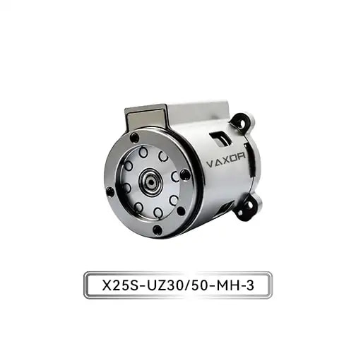
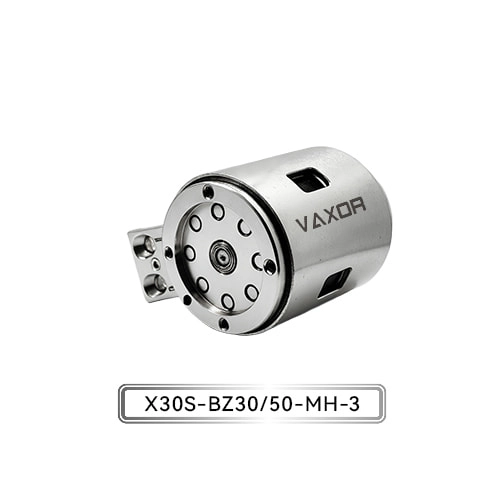
The Φ30mm Micro Joint Actuator is designed for medium-to-high load applications, with Newton-meter-level output capability and high structural rigidity. For humanoid robot developers, evaluating this actuator begins with a practical question: how much torque does the elbow actually need to deliver under its most demanding operating conditions?
Identify the Loads Acting on a Humanoid Robot Elbow
An elbow joint typically supports several components, including the forearm structure, wrist assembly, end effector, and any object being handled. Each component contributes to the total load, but its effect on the elbow depends on its mass and distance from the joint axis.
Three load categories should be included in the initial calculation.
The first is the structural load. The forearm, wrist, motorized tools, wiring, and other components all contribute to the mass that the elbow must move. Even when the robot is not carrying an external object, the weight of its own arm can create a significant torque requirement.
The second is the payload. A humanoid robot designed to pick up small components may operate with a relatively light gripper, while a robot handling larger objects must accommodate a different load profile. Engineers should define the maximum intended payload rather than relying solely on the average object weight.
The third is the dynamic load. When the arm accelerates, decelerates, or changes direction, the elbow must overcome rotational inertia in addition to gravitational torque and mechanical friction. Rapid movement can therefore require considerably more torque than slow, controlled positioning.
These loads should be assessed together. A joint that performs adequately during an unloaded demonstration may not provide sufficient performance when the forearm is extended and carrying its maximum specified payload.
Calculate the Elbow Joint's Gravitational Torque
A useful first step is to estimate the torque generated by gravity. For a component whose center of mass is offset from the joint axis, the gravitational torque can be expressed as:
Torque = Mass × Gravitational Acceleration × Perpendicular Distance
Here, mass is measured in kilograms, gravitational acceleration is approximately 9.81 m/s², and perpendicular distance is measured in meters. The resulting torque is expressed in newton-meters (N·m).
Consider a simplified example in which the combined forearm assembly and payload have a mass of 1.2 kg, with their combined center of mass located 0.15 m from the elbow axis. When the arm is horizontal, the approximate gravitational torque is:
1.2 × 9.81 × 0.15 = 1.77 N·m
This result represents the gravitational torque for the assumed combined mass and center-of-mass location. It does not include acceleration, friction, transmission losses, or additional design margins.
The example also illustrates why payload mass alone is not enough to determine actuator size. A lighter object positioned farther from the elbow can create a similar torque to a heavier object held closer to the joint.
Joint orientation matters as well. When the forearm rotates, the perpendicular distance between the joint axis and the gravitational force changes. The maximum gravitational torque may occur when the arm is approximately horizontal, depending on the mass distribution and movement range.
For an initial sizing estimate, engineers should calculate the torque across the relevant joint angles and identify the position that produces the highest demand.
Include Acceleration and Rotational Inertia
Gravitational torque is only part of the elbow's operating requirement. A humanoid robot must also accelerate the forearm and its payload during movement.
For rotational motion, the inertial torque can be approximated by:
Inertial Torque = Moment of Inertia × Angular Acceleration
Moment of inertia describes how the mass is distributed around the rotation axis, while angular acceleration describes how quickly the joint's rotational speed changes.
The total required output torque can be estimated as:
Required Torque = Gravitational Torque + Inertial Torque + Frictional Torque
This simplified relationship is useful for preliminary sizing, although a complete model may also need to account for coupling between joints, transmission efficiency, compliance, and other dynamic effects.
For example, an elbow that moves slowly between two positions may be dominated by gravitational loading. A joint that repeatedly lifts, stops, reverses direction, and lowers an object may experience greater transient torque demands.
Engineers should therefore define a representative motion profile before selecting an actuator. Relevant parameters include angular range, peak speed, acceleration, deceleration, cycle frequency, and the duration of stationary holding periods.
A realistic motion profile also helps distinguish short-duration torque peaks from the torque required throughout normal operation.
Compare Continuous Torque With Short-Duration Torque
Once the load calculation is complete, the next step is to compare the result with the actuator's performance specifications. Two values deserve particular attention: continuous torque and initial torque.
Continuous torque is relevant when an actuator must operate under sustained mechanical demand. The permissible value depends on the manufacturer's specified conditions, including operating speed, thermal environment, and duty cycle. A joint that repeatedly holds a load or moves for extended periods must be evaluated against the applicable continuous operating limits.
Initial torque describes a short-duration capability associated with starting or overcoming a demanding load, according to the product specification. It should not be treated as a level that the actuator can deliver indefinitely.
The Φ30mm Micro Joint Actuator has a specified continuous torque of up to 1500 mN·m and an initial torque of up to 2200 mN·m. These figures provide a useful starting point for comparing the actuator with the calculated elbow load.
For reference, 1500 mN·m equals 1.5 N·m, while 2200 mN·m equals 2.2 N·m. In the simplified 1.77 N·m example above, the gravitational torque alone exceeds the stated maximum continuous torque. The example would therefore require a more detailed assessment rather than an assumption that the actuator is suitable.
This comparison is important because a maximum initial torque above the calculated load does not establish that the joint can sustain that load. Engineers must determine whether the actual torque demand remains within the appropriate continuous rating and whether transient peaks are permitted under the specified operating conditions.
If the demand is too high, possible design responses include reducing the payload, moving the center of mass closer to the joint, changing the arm geometry, adjusting the movement profile, or evaluating another actuator configuration.
Evaluate the Gear Ratio and Output Speed
The gear ratio affects the relationship between motor speed and output torque. A higher reduction ratio generally provides greater output torque for a given motor torque, while reducing output speed. Actual performance also depends on transmission efficiency, motor characteristics, and operating conditions.
The VAXOR actuator model X30S-UZ/BZ30/50-MH-3 is available with gear ratios of 30 and 50. These configurations offer different starting points for balancing output torque and joint speed.
For a humanoid elbow, the correct ratio depends on how the robot will be used. An arm designed for controlled manipulation may prioritize adequate torque and stable positioning, while an arm intended for faster gestures or frequent movements may require closer attention to speed and dynamic response.
Engineers should compare the output speed and torque available at the required operating points rather than assuming that the higher ratio is always preferable. The reducer's influence on inertia, mechanical response, and overall motion behavior should also be considered.
Where multiple joints move together, the elbow should be evaluated as part of the complete arm. A change in elbow speed or acceleration can affect the motion requirements of the shoulder and wrist, particularly when the robot follows a coordinated trajectory.
Consider Weight, Voltage, and Control Integration
An actuator's torque capability is only one part of the mechanical design. Its weight affects the load carried by upstream joints, while its electrical and communication requirements influence system integration.
The Φ30mm actuator has a specified weight of 123–133 g and an operating voltage range of 12–18 V. When evaluating the unit, engineers should use the weight of the relevant configuration and include mounting hardware, cables, connectors, and other components in the total moving-mass calculation.
This is particularly important for humanoid arms with multiple actuated joints. Additional mass near the elbow can increase the torque required from the shoulder, creating a cascading effect across the arm.
Electrical compatibility should be checked at the same time. The power supply must remain within the specified voltage range under realistic operating conditions, and its current capacity must support the actuator's actual demand during acceleration and other high-load events. Voltage compatibility alone does not establish that a power system is adequate.
The actuator also uses an absolute magnetic encoder and supports CAN FD communication. The encoder provides position feedback, while CAN FD supports communication with a compatible control system. Engineers should verify interface configuration, message timing, feedback requirements, fault handling, and controller compatibility during integration.
These checks help ensure that the selected actuator can be incorporated into the intended robotic architecture without treating its mechanical specification as a complete system-level performance guarantee.
Validate the Selection Through Representative Testing
Analytical calculations provide a starting point, but a working humanoid robot introduces real-world variables that may not be fully captured by a simplified model.
Before committing to a final design, engineers should test the actuator in a representative joint assembly. The test should reflect the intended arm geometry, payload range, movement speed, acceleration, and operating cycle.
Several measurements can help validate the selection:
Output torque: Confirm that the joint can meet its required load conditions without exceeding the applicable operating limits.
Temperature behavior: Monitor temperature during representative cycles to identify potential thermal limitations.
Position control: Evaluate positioning repeatability and response during loaded movements.
Dynamic response: Check acceleration, deceleration, reversal, and stopping behavior.
Communication stability: Verify that command and feedback exchange remain reliable under the intended control conditions.
Mechanical stability: Inspect mounting rigidity, vibration, and unwanted movement under load.
Testing should include the most demanding intended operating conditions, not just short unloaded movements. If the elbow must hold a load for extended periods, sustained operation should be included in the validation plan.
The results can then guide adjustments to the payload limit, motion profile, gear ratio, mechanical layout, or actuator configuration before the design proceeds to broader integration.
Working With an Integrated Micro-Drive Solution
Selecting an actuator for a humanoid elbow involves motor performance, reduction mechanics, position feedback, structural design, and manufacturing considerations. Evaluating these elements together can make it easier to identify integration issues early in the development process.
Founded in 2024 and headquartered in Suzhou, China, VAXOR develops micro joint actuators and ultra-micro coreless motors for robotics, precision instruments, medical devices, and intelligent equipment. Its technology approach combines axial-flux motor design, PCB/FPCB winding, optimized electromagnetic design, and miniature reduction mechanisms.
The company's multidisciplinary team works across motor design, precision manufacturing, robotics control, and structural engineering, with experience spanning prototype validation, pilot production, and batch delivery. This engineering focus is relevant to development teams that need to assess a micro-drive solution not only against a torque target but also against mechanical packaging, control integration, and production requirements.
For humanoid robot developers, the practical objective is to establish a clear relationship between the joint's calculated load, the actuator's verified operating capability, and the robot's intended motion profile.
Conclusion
Sizing an actuator for a humanoid robot elbow requires a systematic assessment of gravitational torque, rotational inertia, acceleration, continuous operating demand, and the effects of actuator mass on the rest of the arm. Gear ratio, encoder feedback, electrical compatibility, and communication requirements must also fit the overall design.
The Φ30mm Micro Joint Actuator, model X30S-UZ/BZ30/50-MH-3, offers continuous torque up to 1500 mN·m, initial torque up to 2200 mN·m, gear ratios of 30 and 50, an absolute magnetic encoder, and CAN FD communication. These specifications provide a basis for evaluating the actuator in medium-to-high load robotic joints, but final suitability depends on the required output performance and operating conditions.
By calculating the load before selecting the drive and validating the complete joint under representative conditions, engineers can make more reliable decisions about actuator sizing and humanoid arm integration. VAXOR provides micro-drive solutions for development teams working toward compact, controlled, and mechanically integrated robotic systems.