 Store
Store
 EN
EN CN
CN VI
VI IT
IT ES
ES TH
TH JA
JA PT
PT MS
MS KO
KO FR
FR DE
DE ID
IDCollaborative robots need to perform accurate, repeatable movements while operating within tight space and weight limits. Whether a robot is handling small components, assisting with laboratory tasks, or performing delicate assembly, its joint actuator must provide enough torque to move the load without compromising positioning accuracy or response speed. Selecting an actuator based on torque alone, however, can lead to problems with stability, power consumption, and mechanical integration.
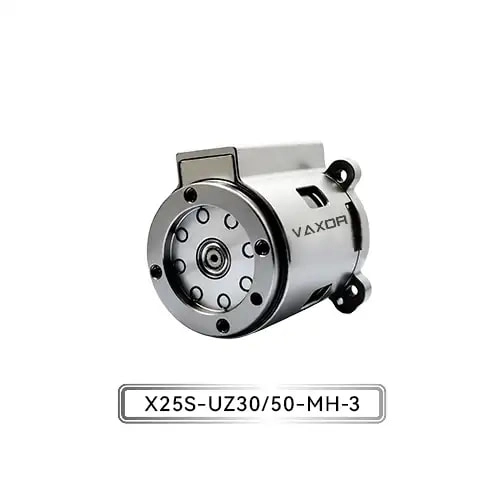
For engineers developing compact robotic joints, torque selection should begin with the actual load conditions and the intended movement profile. The relationship between payload, joint geometry, acceleration, and reduction ratio determines how much torque the drive system needs to deliver. A properly matched Φ25mm Micro Joint Actuator can help balance these requirements in collaborative robots and biomimetic robotic structures where installation space is limited.
Why Torque Matching Matters in Collaborative Robots
In a collaborative robot, every joint contributes to the movement of the entire mechanism. A shoulder joint supporting an extended arm faces different demands from a wrist joint rotating a lightweight gripper. Even when both joints use compact actuators, their torque requirements can differ substantially.
Three operating conditions deserve particular attention.
First, the actuator must support the static load. When a robotic arm holds an object without moving, gravity may create a continuous torque demand at the joint. This demand increases when the payload is heavier or positioned farther from the joint axis.
Second, the actuator must handle acceleration and deceleration. Starting, stopping, and reversing direction require additional torque beyond the amount needed to maintain a stationary position. Frequent changes in motion can make peak torque capability particularly important.
Third, the actuator must maintain acceptable motion quality. An actuator that can move a load but struggles to control it accurately may cause vibration, positioning errors, or inconsistent handling. Engineers therefore need to evaluate torque alongside encoder feedback, communication performance, and the mechanical characteristics of the complete joint.
These factors explain why choosing a micro actuator simply because its dimensions fit the robot is not enough. The drive must meet the actual mechanical demands of the application.
Calculate the Torque Required by the Joint Load
A practical starting point is to estimate the torque generated by the payload and other components supported by the joint. For a load acting at a distance from the rotation axis, the gravitational torque can be approximated by:
Torque = Mass × Gravitational Acceleration × Perpendicular Distance
For example, consider a joint supporting a 0.5 kg load whose center of mass is 0.1 m from the joint axis. When the arm is horizontal, the approximate gravitational torque from that load is:
0.5 × 9.81 × 0.1 = 0.4905 N·m
This is equivalent to approximately 491 mN·m. The calculation accounts only for the specified load, not the weight of the robot links, gripper, cables, or other components. Those contributions must also be considered where they create torque around the joint.
Dynamic operation introduces additional requirements. A simplified rotational model is:
Required Torque = Inertial Torque + Gravitational Torque + Frictional Torque
The inertial component depends on the rotational inertia of the moving assembly and its angular acceleration. The gravitational component changes with joint orientation, while friction and transmission losses affect the torque available at the output.
In practice, engineers should evaluate the most demanding operating positions and movement profiles rather than relying on a single static calculation. The resulting torque requirement can then be compared with the actuator's continuous and initial torque specifications.
Understand Continuous Torque and Initial Torque
Continuous torque and initial torque describe different aspects of actuator performance. Treating them as interchangeable can lead to an unsuitable selection.
Continuous torque indicates the torque an actuator can sustain under specified operating conditions. It is especially relevant when a joint must hold or move a load for extended periods. The allowable continuous output depends on factors such as thermal conditions, operating speed, duty cycle, and the manufacturer's rating method.
Initial torque describes a short-duration torque capability associated with starting or overcoming a demanding load, according to the applicable product specification. It can help assess brief operating demands, but it should not be treated as a torque level available continuously.
The Φ25mm Micro Joint Actuator from VAXOR provides a specified continuous torque of up to 1150 mN·m and an initial torque of up to 1800 mN·m. These figures give engineers useful reference points when assessing compact joint applications. They do not, by themselves, establish suitability for every payload or duty cycle; the operating conditions and detailed performance curves must also be considered.
A sound selection process keeps sustained torque demand within the applicable continuous operating limits and verifies that short-duration demands remain within the permitted peak or initial operating conditions.
Select the Gear Ratio for the Required Motion
The gear ratio affects the relationship between motor speed and output torque. A higher reduction ratio generally increases the torque available at the output while reducing output speed, subject to transmission efficiency and the characteristics of the motor and reducer.
For collaborative robots, this creates a practical trade-off. A joint designed for controlled positioning under a relatively heavy load may benefit from a different reduction ratio than a joint intended for rapid movement with a lightweight end effector.
The VAXOR Φ25mm actuator is available with gear ratios of 30 and 50. These options provide a starting point for evaluating different combinations of output speed and torque requirements.
When comparing the two ratios, engineers should consider the complete movement profile. Important questions include:
What output speed is needed during normal operation?
How much torque is required during acceleration and deceleration?
Does the joint need to change direction frequently?
How much mechanical inertia does the transmission add?
Can the actuator maintain the required positioning accuracy under the expected load?
A higher ratio should not automatically be considered the better option. The final choice depends on the balance between torque, speed, responsiveness, and control requirements. Engineers should confirm the available output performance for each configuration before finalizing the design.
Evaluate Feedback and Communication Requirements
Torque capacity determines whether a joint can generate sufficient mechanical force, but feedback and communication determine how effectively the robot can coordinate that movement.
An absolute encoder provides position information referenced to an absolute position within its specified measurement range. Depending on the encoder design and system architecture, this can simplify position initialization and support consistent joint-position feedback. Engineers should still verify resolution, accuracy, interface requirements, and startup behavior for the intended application.
The VAXOR micro joint actuator uses an absolute magnetic encoder and supports CAN FD communication. These features are relevant to robotic systems that need position feedback and integration with a compatible controller network.
CAN FD supports flexible data rates and larger payloads than classical CAN, making it useful in control architectures that exchange a variety of motion and status information. However, the actuator and controller must be configured for compatible communication settings, message structures, timing, and network requirements.
During integration, engineers should test position feedback, command response, fault handling, and behavior under changing loads. These checks help establish whether the complete joint system meets the application's control requirements, rather than assuming that a particular encoder or communication interface guarantees performance on its own.
Account for Size and Weight Constraints
Compact actuator selection is also a mechanical packaging problem. Every additional gram in a moving robotic link can increase the torque required from upstream joints. A heavier wrist assembly, for example, can raise the load carried by the elbow and shoulder even when the payload itself remains unchanged.
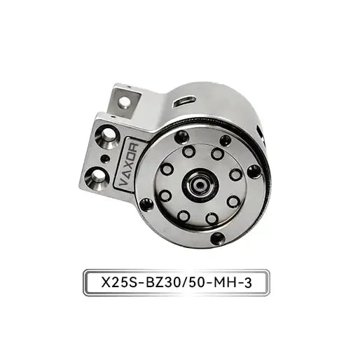
The Φ25mm Micro Joint Actuator, model X25S-UZ/BZ30/50-MH-3, has a specified weight of 93–103 g and operates at 12–18 V. Its compact format is relevant to collaborative robots, biomimetic joints, and other motion systems where installation space and moving mass are restricted.
The listed weight range should be checked against the exact configuration being evaluated. Engineers should also account for mounting structures, wiring, connectors, cooling provisions where applicable, and any additional mechanical components required for installation.
For battery-powered robots and mobile equipment, voltage compatibility and power demand deserve particular attention. The available supply must remain within the specified operating range under realistic load conditions. The electrical design should also consider current demand during acceleration, startup, and other high-load events.
Reducing actuator mass can benefit the overall robot, but weight should never be evaluated independently of torque capacity, thermal performance, and the structural demands of the joint.
Match the Actuator to Real Operating Scenarios
Different robotic applications create different combinations of load, speed, and precision requirements.
In a collaborative assembly robot, a joint may repeatedly position small components along a defined path. Engineers need to account for the mass of the tool, the component being handled, the distance from the joint axis, and the frequency of repeated movements.
In a compact robotic gripper, the actuator may need to deliver controlled movement within a restricted installation envelope. The selection process should consider the required output torque, available travel or rotation, response characteristics, and the mechanical design of the gripping mechanism.
Biomimetic robots introduce another set of demands. Their joints may need to coordinate multiple movements while keeping the mechanism lightweight. Depending on the design, engineers may need to balance torque output against speed, repeated motion, and the behavior of the overall linkage.
For medical devices and precision instruments, the evaluation may place greater emphasis on controllability, repeatability, noise, and integration constraints. Suitability depends on the specific device requirements, including any applicable safety, cleanliness, reliability, or regulatory standards. A compact actuator specification alone does not establish that a complete system is suitable for a particular medical application.
Across these scenarios, the most reliable approach is to define measurable operating requirements first and then compare actuator configurations against them.
Consider the Integrated Drive Design
A micro joint actuator combines several components whose interaction affects the final result. Motor electromagnetic design influences torque production and efficiency. The reduction mechanism changes the relationship between motor output and joint movement. Encoder feedback and control electronics support positioning and coordinated operation.
VAXOR develops micro joint actuators and ultra-micro coreless motors for robotics, medical devices, precision instruments, and intelligent equipment. Founded in 2024 and headquartered in Suzhou, China, the company brings together expertise in motor design, precision manufacturing, structural engineering, and robotics control.
Its micro-drive development approach integrates axial-flux motor technology, PCB/FPCB winding, optimized electromagnetic design, and miniature reduction mechanisms. The aim is to address practical engineering requirements such as compact dimensions, high torque density, fast response, and consistent production.
For engineers evaluating an integrated actuator, this system-level perspective is important. Instead of assessing the motor, reducer, and encoder in isolation, the complete assembly should be reviewed against the joint's load profile, installation constraints, controller architecture, and production requirements. Prototype validation and testing under representative operating conditions can then identify issues before the design moves toward larger-scale deployment.
A Practical Checklist Before Final Selection
Before integrating a micro actuator into a collaborative robot, review the following points:
Calculate the load: Include the payload, links, gripper, and other components that contribute to joint torque.
Define the motion profile: Identify the required speed, acceleration, deceleration, movement frequency, and holding conditions.
Separate continuous and short-duration demands: Compare sustained torque with continuous ratings and verify transient demands against the applicable limits.
Choose the reduction ratio: Evaluate the balance between output torque, speed, and dynamic response.
Confirm electrical and control compatibility: Check the operating voltage, encoder requirements, communication interface, and controller configuration.
Verify mechanical integration: Review dimensions, mounting, total moving mass, and cable routing.
Test the complete assembly: Validate performance under realistic loads, duty cycles, temperatures, and movement sequences.
This process turns actuator selection from a specification comparison into an engineering decision based on measurable operating conditions.
Conclusion
Matching actuator torque to collaborative robot loads requires more than finding a unit with a sufficiently high torque rating. Engineers must account for gravity, inertia, acceleration, transmission ratio, feedback, electrical supply, and the effect of actuator mass on the wider mechanism.
The Φ25mm Micro Joint Actuator offers a compact drive option with continuous torque up to 1150 mN·m, initial torque up to 1800 mN·m, gear ratios of 30 and 50, an absolute magnetic encoder, and CAN FD communication. These specifications provide a basis for evaluating its role in compact robotic joints, subject to confirmation of the required operating conditions and detailed performance data.
By defining the load profile first and validating the integrated drive under realistic conditions, engineers can make more informed decisions about torque capacity, motion performance, and mechanical integration. With its focus on integrated micro-drive technology, VAXOR supports engineering teams working to develop compact and responsive robotic systems.