 Store

 EN
 CN
 VI
 IT
 ES
 TH
 JA
 PT
 MS
 KO
 FR
 DE
 ID
Choosing a motor for a precision motion system involves more than checking its diameter or maximum rotational speed. Engineers need to understand how the motor behaves under load, how it interacts with the power supply and transmission mechanism, and whether its performance can be maintained in the final application. These factors become especially important when the available installation space is only a few millimeters.
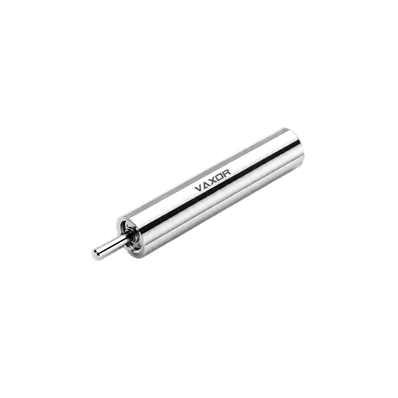
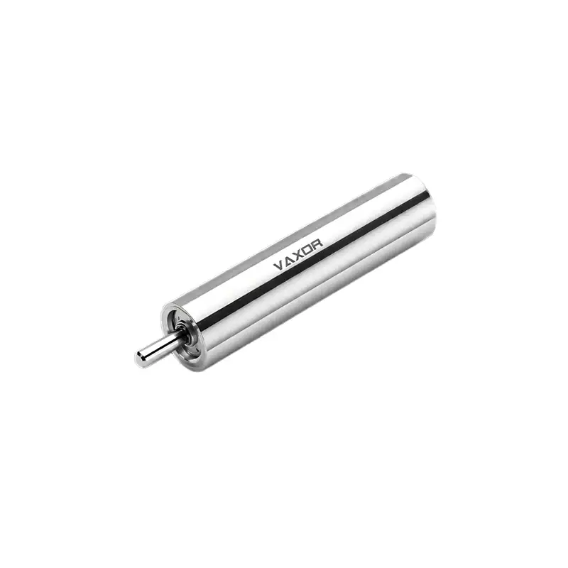
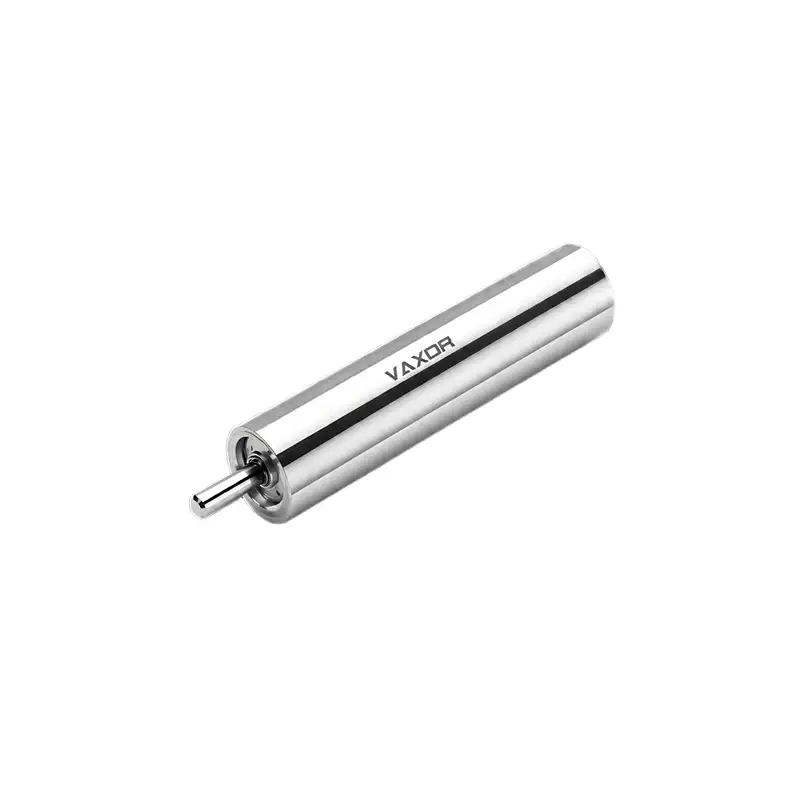
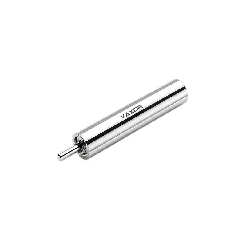
The φ5mm Ultra-micro Brushless Coreless Motor is designed for applications where compact dimensions, high rotational speed, and practical manufacturability must work together. Its specifications provide a useful starting point for evaluating whether a miniature motor can meet the requirements of a precision device, from compact robotic mechanisms to wearable electronics and selected UAV subsystems.
A structured evaluation process helps engineers move beyond headline specifications and make decisions based on actual operating conditions.
1. Start with the Real Requirements of the Motion System
Before comparing motors, define what the mechanism needs to do. A motor that performs well in one application may be unsuitable for another, even when both devices have similar size constraints.
Start by identifying the available installation space, required output speed, expected load, duty cycle, supply voltage, and acceptable levels of vibration and noise. Also consider whether the motor will operate continuously or in short bursts, and whether it will drive a mechanism directly or through a gearbox.
For example, a compact wearable device may prioritize low weight and limited heat generation, while a miniature robotic mechanism may place greater emphasis on repeatable movement and predictable response under changing loads.
The φ5mm Ultra-micro Brushless Coreless Motor, model G05P-VW00-QZ-1, has a listed weight of 2.6 g and a nominal voltage of 6 V. These figures help engineers assess the mechanical and electrical constraints early in the design process. However, they should be evaluated alongside the load profile and operating environment rather than treated as proof of suitability on their own.
2. Understand No-Load Speed and Nominal Speed
Rotational speed is an important specification, but different speed ratings describe different operating conditions.
The G05P-VW00-QZ-1 has a no-load speed of 55,000 rpm and a nominal speed of 30,000 rpm. No-load speed describes operation with no external mechanical load applied to the motor shaft, whereas nominal speed represents a specified operating condition under load. The precise test conditions and rated operating point should be confirmed in the manufacturer's technical documentation.
The difference matters because a motor rarely operates without resistance in a real mechanism. Bearings, gears, friction, aerodynamic effects, and the driven component all influence the final speed.
When evaluating a motor for precision motion, ask three practical questions:
What speed is required at the motor shaft under the expected load?
Will a gearbox or other transmission be used to reduce speed or increase output torque?
Does the mechanism need to maintain a stable speed across different operating conditions?
If the application requires controlled movement rather than maximum rotational speed, the relevant comparison is the motor's performance at the intended working point. Engineers should request speed-torque curves and operating-condition data where available, rather than estimating loaded performance from the no-load figure alone.
3. Match Rated Torque to the Mechanical Load
Torque determines how effectively a motor can drive a load. For miniature mechanisms, even small differences in torque requirements can influence the choice of motor, transmission, and control strategy.
The listed nominal torque of the φ5mm Ultra-micro Brushless Coreless Motor is 0.40 mNm, while its stalling torque is 0.80 mNm. These values describe different conditions and should not be treated as interchangeable. Stalling torque refers to the torque associated with a stationary rotor under specified test conditions; it does not mean that continuous operation at this level is recommended.
To evaluate torque suitability, estimate the torque needed to overcome friction, accelerate moving components, and maintain motion against the external load. If the mechanism includes gears, account for the gear ratio and transmission efficiency when calculating the output torque and speed.
A reduction mechanism can increase output torque while lowering speed, but it also introduces losses, backlash, and additional mechanical constraints. The complete assembly therefore needs to be evaluated as a system.
It is also important to leave an appropriate design margin for load variation, wear, manufacturing tolerances, and transient operating conditions. The required margin depends on the application and should be established through engineering calculations and testing rather than an arbitrary multiplier.
4. Check Electrical Compatibility Beyond the 6 V Rating
A motor's nominal voltage is only one part of its electrical requirements. The power supply, motor driver, wiring, and control strategy must all support the intended operating conditions.
The G05P-VW00-QZ-1 is specified at 6 V, with a torque constant of 0.65 mNm/A. The torque constant describes the relationship between motor current and torque under the applicable motor model and test conditions. It can help engineers estimate current demand, but it should not replace measured performance data or the manufacturer's current ratings.
Before integrating the motor, confirm its operating current, startup behavior, permissible current limits, and thermal characteristics. These details are particularly important in battery-powered products, where peak current may affect power delivery and battery life.
The driver should also be selected to provide the required speed control and response without exceeding the motor's electrical or thermal limits. If the application requires frequent acceleration and deceleration, testing should reproduce those conditions rather than relying only on steady-state measurements.
5. Evaluate Size, Weight, and Manufacturability Together
A 5 mm motor can help free up space in compact products, but a small motor does not automatically produce a smaller or easier-to-manufacture system. The mounting structure, connectors, transmission components, wiring, and surrounding enclosure also occupy space.
At 2.6 g, this motor offers a defined weight reference for a system's mass budget. Engineers should include the mass of any gearbox, bracket, coupling, and supporting structure when estimating the weight of the complete drive assembly.
Manufacturability deserves the same attention. Small components can place demanding requirements on assembly alignment, tolerances, handling, and inspection. A design that performs well in a single prototype may require additional validation before it can be produced consistently at volume.
VAXOR's approach combines micro-motor development with a focus on engineering implementation, prototype validation, pilot production, and batch delivery. Its technical roadmap includes optimized electromagnetic design and PCB/FPCB winding technologies. For an OEM project, the practical questions are whether the supplier can support the required interfaces, provide relevant test documentation, and maintain the specifications needed for production.
6. Consider the Role of FPCB Winding and AI-Optimized Design
Winding technology and electromagnetic design influence how a miniature motor balances performance, packaging, and manufacturing requirements. FPCB winding can support compact winding layouts, while design optimization can help engineers evaluate competing constraints during development.
However, the value of these technologies should be judged by measurable results rather than the technology names alone. Ask which performance requirements the design is intended to address, what test methods are used, and whether the results can be reproduced across multiple units.
For example, an evaluation may compare speed and current under defined loads, dimensional consistency, operating temperature, and repeatability across samples. The exact test plan will depend on the application and the available product documentation.
AI-optimized design can form part of the engineering process, but it should not be interpreted as a guarantee of superior performance in every application. The final decision still depends on verified specifications, mechanical integration, and testing under representative conditions.
7. Validate the Motor in the Actual Application
Once the initial calculations indicate a suitable candidate, test the motor in a representative assembly. Begin with basic checks of dimensions, mounting, electrical connections, and rotation. Then measure speed and current under several relevant load conditions.
For systems that repeatedly start, stop, or change direction, reproduce the expected operating cycle. Monitor temperature and inspect the assembly for unwanted vibration, noise, or mechanical interference. Where long service life is important, establish an endurance test based on the application's duty cycle and acceptance criteria.
The φ5mm Ultra-micro Brushless Coreless Motor may be considered for UAV mechanisms, wearable products, and other compact motion systems, but suitability should be confirmed separately for each use case. Environmental conditions, shock and vibration exposure, control requirements, and the driven load can differ substantially between applications.
Before moving from prototype to production, document the test conditions and acceptance limits. This makes it easier to compare samples, investigate performance variation, and communicate requirements between engineering, purchasing, and manufacturing teams.
8. Make the Decision Based on System-Level Performance
A reliable motor selection process combines mechanical, electrical, and manufacturing considerations. No-load speed helps describe the motor's speed capability, nominal speed and torque provide a starting point for evaluating the working range, and voltage and torque constant help frame the electrical assessment. Weight and dimensions then inform packaging and integration.
For engineering teams developing compact, intelligent equipment, VAXOR works across micro joint actuators and ultra-micro coreless motors, with technical expertise spanning motor design, precision manufacturing, robotics control, and structural design. Its focus on moving from prototype validation toward scalable production is relevant when a project needs more than a component that works in a laboratory demonstration.
The final choice should be based on documented operating conditions, realistic load calculations, electrical compatibility, and validation in the target mechanism. By evaluating these factors together, engineers can determine whether the φ5mm Ultra-micro Brushless Coreless Motor meets their requirements and identify any design changes needed before committing to production.