 Store

 EN
 CN
 VI
 IT
 ES
 TH
 JA
 PT
 MS
 KO
 FR
 DE
 ID
As electronic products become smaller, integrating a motor into a limited space requires careful coordination between mechanical design, power electronics, and control systems. The challenge is not simply finding a motor that fits. Engineers must also ensure that the power supply can support its operating requirements, the driver can control its speed reliably, and the assembled system can manage heat and mechanical loads during normal use.
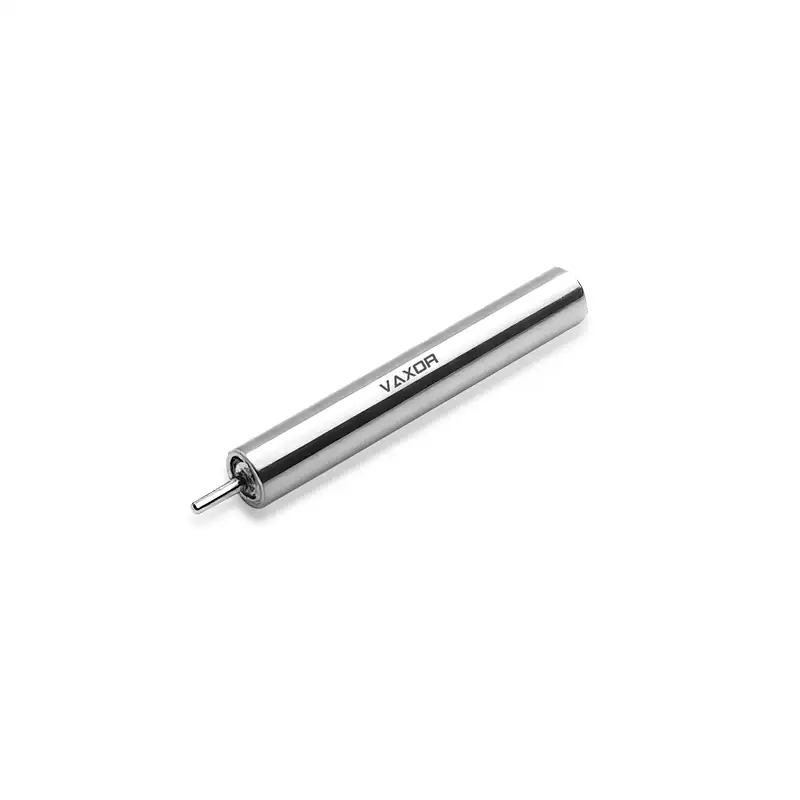
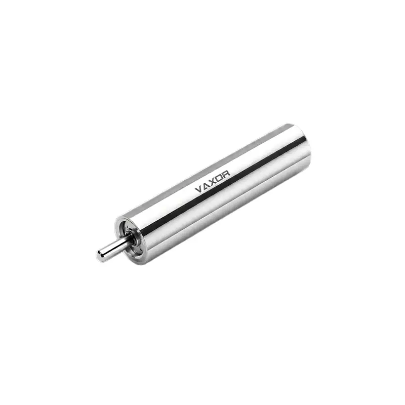
The φ6mm Ultra-micro Brushless Coreless Motor is designed for miniature applications that require high rotational speed and increased torque output within a compact footprint. Its 12 V nominal voltage, 3.75 g weight, and defined speed and torque specifications provide a starting point for evaluating its suitability for compact electronic systems.
For product developers, the most effective approach is to assess the motor as part of the complete assembly rather than as an isolated component. The following considerations can help reduce integration problems during prototyping and prepare the design for production.
1. Confirm the Electrical Requirements Before Selecting the Driver
The first step is to check whether the available power supply and motor driver are compatible with the motor's electrical requirements.
The G06P-VW00-QZ-1 model has a nominal voltage of 12 V. This provides a reference for selecting the supply and driver, but it does not establish every electrical limit. Engineers should obtain the manufacturer's current ratings, permissible voltage range, startup characteristics, and thermal limits before finalizing the circuit.
The driver must support the required operating voltage and supply sufficient current during startup and changing loads. Its continuous and peak current capabilities should be evaluated separately. A driver that operates correctly when the motor is unloaded may encounter current limiting or protection shutdown when the motor accelerates a mechanism.
It is also important to consider the rest of the electronic system. If the motor shares a supply with sensors, communication modules, processors, or other sensitive components, sudden changes in motor current may affect supply stability. Power distribution, grounding, decoupling, and electrical noise control should therefore be addressed during circuit design.
2. Understand the Difference Between Speed Ratings
Motor speed specifications help determine whether a component can meet an application's motion requirements, but the operating conditions behind each figure matter.
The φ6mm Ultra-micro Brushless Coreless Motor has a listed no-load speed of 63,000 rpm and a nominal speed of 45,000 rpm. No-load speed describes operation without an external mechanical load on the shaft. Nominal speed refers to a specified operating condition under load, which should be confirmed in the manufacturer's documentation.
In a real electronic product, the motor must overcome mechanical resistance from bearings, couplings, gears, and the driven mechanism. These loads influence the actual operating speed. Engineers should therefore avoid using the no-load figure as the expected speed of the finished device.
During integration, measure speed under representative operating conditions. If the mechanism repeatedly accelerates, decelerates, or changes load, include these situations in testing. This helps establish whether the motor can meet the required response and speed range in the actual assembly.
Where the application requires lower output speed or greater output torque, a reduction mechanism may be worth evaluating. However, the additional transmission introduces its own losses, dimensional requirements, and mechanical tolerances.
3. Match Torque Output to the Driven Mechanism
A motor's torque rating determines how much rotational effort it can provide under specified operating conditions. Matching this capability to the load is essential for avoiding slow response, excessive current demand, and unreliable operation.
For model G06P-VW00-QZ-1, the listed nominal torque is 0.49 mNm, while the stalling torque is 0.98 mNm. These figures describe different operating conditions. Stalling torque should not be treated as the recommended continuous operating torque because a stationary rotor may draw substantial current and generate heat.
Start by estimating the torque required to overcome friction, accelerate the moving parts, and maintain motion against external resistance. For mechanisms with gears or other transmission components, account for their efficiency when calculating output torque and speed.
The design should also allow for variations in load, assembly tolerances, and operating conditions. If the mechanism must start reliably from rest or handle frequent changes in resistance, test those conditions rather than evaluating only steady-state operation.
The objective is to identify a practical working point where speed, torque, current demand, and thermal behavior remain within the manufacturer's specified limits.
4. Use the Torque Constant to Support Current Estimates
The torque constant provides another useful reference during electrical and mechanical integration. The G06P-VW00-QZ-1 has a listed torque constant of 1.05 mNm/A.
Under the applicable motor model and test conditions, the torque constant describes the relationship between motor current and electromagnetic torque. Engineers can use it to develop an initial estimate of the current needed for a target torque.
However, this estimate is not a substitute for measured operating data. Friction, driver behavior, transient loads, and the exact conditions used to characterize the motor can affect the relationship between current and delivered mechanical output.
Before selecting the driver, request the relevant current specifications and performance curves. Then measure current at startup, under representative loads, and during the expected operating cycle. These measurements help determine whether the power supply, wiring, and protection settings are appropriate for the application.
5. Plan Mechanical Installation Around the Complete Assembly
A motor with a 6 mm diameter can help reduce the space required for a drive system, but the complete installation needs more room than the motor body alone.
Allow space for mounting features, electrical connections, shaft coupling, any reduction mechanism, and access for assembly. Check whether the mounting structure can hold the motor securely without introducing unwanted misalignment or excessive mechanical stress.
Alignment is particularly important when the motor drives a small gear train or precision mechanism. Poor alignment can increase friction, create vibration, and reduce the consistency of operation. The mounting design should also prevent loads from being transferred to parts of the motor that are not intended to support them.
The listed weight of 3.75 g is useful when calculating the product's mass budget. However, the final weight should include the motor mount, wiring, driver board, and any transmission components.
For compact electronics, it is often helpful to build a representative mechanical mock-up early. This can reveal conflicts involving connectors, enclosure walls, assembly access, or nearby electronic components before the design is finalized.
6. Manage Heat and Electrical Interference
Thermal management is an important part of miniature motor integration because limited space can restrict airflow and heat dissipation. The motor's actual temperature depends on factors such as current, load, operating duration, ambient conditions, and the thermal characteristics of the surrounding assembly.
A small enclosure should not be assumed to provide adequate cooling simply because the motor itself is compact. Test the motor under the expected duty cycle and monitor temperature at appropriate locations. Continuous operation, frequent starts, and high-load periods may produce different thermal conditions.
Electrical interference also deserves attention. Switching circuits and changing motor currents can introduce noise into nearby signal lines. Depending on the system, practical measures may include careful PCB layout, suitable grounding, supply decoupling, and separating sensitive signal paths from motor power routing.
These measures should be verified through testing. A design that works on an open bench may behave differently after the motor, driver, sensors, and control electronics are installed inside the final enclosure.
7. Validate the Design Before Moving to Production
A structured validation process helps identify problems before they become expensive to correct. Begin with basic checks of supply voltage, connections, rotation, and mounting. Then measure speed and current at several representative load points.
Next, reproduce the intended operating cycle. Check startup behavior, repeated acceleration, temperature rise, vibration, and any changes in performance after extended operation. Where the device has strict space or noise requirements, test the complete enclosure rather than the motor alone.
Document the test conditions, measured results, and acceptance criteria. This creates a consistent basis for comparing prototypes and later production samples.
VAXOR develops micro joint actuators and ultra-micro coreless motors for robotics, precision instruments, medical devices, and intelligent equipment. Its multidisciplinary engineering team works across motor design, precision manufacturing, structural design, and robotics control, with an emphasis on prototype validation, pilot production, and scalable manufacturing.
For OEM projects, this engineering scope can be relevant when evaluating not only component specifications but also the practical steps required to integrate a motor into a finished product. Technical documentation, sample testing, and clear communication about operating conditions remain essential to the selection process.
8. Evaluate the Motor as Part of the Finished Product
Successful integration depends on how well the motor, driver, power supply, mechanical transmission, and control system work together. Voltage compatibility establishes the electrical starting point, while speed and torque requirements determine whether the motor can perform the intended task. Mounting, thermal management, and validation then help establish whether the complete design is suitable for its operating environment.
The φ6mm Ultra-micro Brushless Coreless Motor offers a defined set of specifications for engineers developing compact motion systems, including a 12 V nominal voltage, 45,000 rpm nominal speed, 0.49 mNm nominal torque, and 3.75 g weight. These figures should be assessed against the application's real load profile and verified using the manufacturer's technical data.
By addressing electrical, mechanical, and thermal requirements early, product teams can reduce integration risks, improve prototype testing, and make better-informed decisions before production. A system-level evaluation is ultimately the most reliable way to determine whether this φ6mm Ultra-micro Brushless Coreless Motor meets the requirements of a compact electronic design.