 Store

 EN
 CN
 VI
 IT
 ES
 TH
 JA
 PT
 MS
 KO
 FR
 DE
 ID
Humanoid robots must maintain stable joint motion while supporting changing loads, accelerating limbs, and responding to external contact. Even when a motor provides sufficient torque, the joint can still deviate from its intended position if the mechanical structure deforms under force. This becomes particularly important in compact joints, where limited installation space must accommodate the motor, reduction mechanism, bearings, encoder, and supporting structure.
Joint stiffness is therefore a key consideration in humanoid robot design. It influences positioning stability, motion consistency, and the ability to maintain a commanded posture under load. For engineers developing compact robotic joints, the challenge is not simply to increase stiffness, but to balance structural rigidity, actuator output, weight, and control performance.
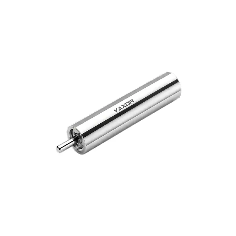
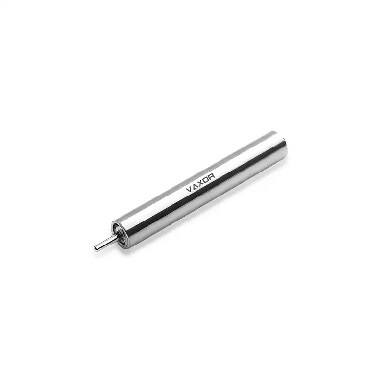
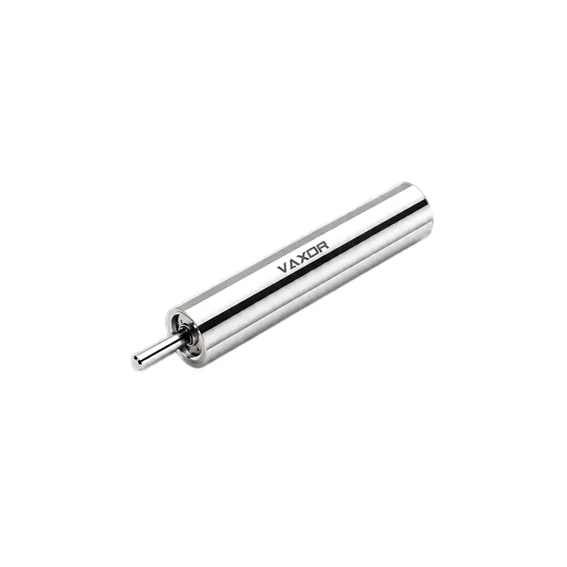
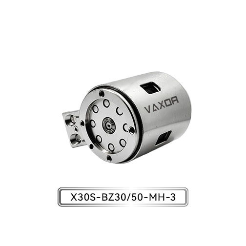
The Φ30mm Micro Joint Actuator is designed for medium-to-high load applications, combining Newton-meter-level output with a compact structure for humanoid robots, exoskeletons, and other robotic joints. Understanding how actuator stiffness interacts with the surrounding mechanical system helps engineers determine whether a joint can maintain the required performance under real operating conditions.
What Joint Stiffness Means in Humanoid Robot Design
Joint stiffness describes how strongly a mechanical joint resists deformation when an external torque or force is applied. In a simplified rotational model, torsional stiffness can be expressed as the applied torque divided by the resulting angular displacement.
A joint with higher stiffness generally experiences less angular deflection under the same applied torque. However, the stiffness of a complete robotic joint does not depend on the actuator alone. The gearbox, bearings, mounting interfaces, fasteners, joint housing, and connected limb structures all contribute to the final result.
For example, an actuator may have a rigid internal structure, but a flexible mounting plate can still allow the joint axis to shift under load. Similarly, clearance in a transmission or looseness at a mechanical interface can introduce positioning errors that cannot be corrected simply by selecting a motor with greater output torque.
This distinction matters in humanoid robots because joints frequently experience changing loads. A leg joint must support body weight and respond to ground contact, while an arm joint may encounter varying loads during reaching, lifting, or manipulation. The design needs to account for both the actuator's output capability and the mechanical path through which that output is transmitted.
How Load-Induced Deflection Affects Robot Motion
Deflection under load can affect several aspects of humanoid robot performance.
First, it can introduce a difference between the commanded joint position and the actual mechanical position. When an external torque acts on a joint, the structure may deform slightly even if the motor and control system continue operating normally. In a multi-joint robot, these small deviations can accumulate along a kinematic chain and produce a larger positional error at the end effector.
Second, deflection can change how loads are distributed between connected joints. If one joint yields more than expected, neighboring joints may need to compensate to maintain the desired posture. This can increase control effort and complicate motion planning, particularly during transitions between static and dynamic movements.
Third, structural compliance can influence the response to contact. During walking, a humanoid robot repeatedly encounters changes in ground reaction forces. During manipulation, an arm may experience unexpected resistance from an object. If the joint structure deforms beyond the expected range, the robot may struggle to maintain its intended trajectory or contact force.
These effects do not mean that every joint should be made as rigid as possible. Some applications benefit from controlled compliance to absorb impacts or improve interaction with people. The engineering objective is to establish an appropriate stiffness range for the task, then verify that the complete joint behaves as expected under its intended loads.
The Role of Actuator Structure in Stiffness
The mechanical design of an actuator influences how effectively torque is transferred to the joint output. Motor construction, reduction mechanism, bearing support, housing geometry, and component alignment all affect the overall behavior of the assembly.
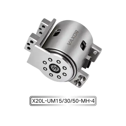
The Φ30mm Micro Joint Actuator is designed around a compact axial-flux motor and miniature cycloidal reduction mechanism. This integrated approach combines motor output and mechanical reduction within a limited installation envelope, supporting applications that require substantial output from a relatively small joint module.
Its specified continuous torque is up to 1500 mNm, equivalent to 1.5 Nm, while the initial torque is up to 2200 mNm, or 2.2 Nm. These figures describe different operating conditions and should not be treated as interchangeable. Continuous torque is relevant when evaluating sustained operation, whereas initial torque is not, by itself, evidence that the actuator can maintain the same output throughout a repeated duty cycle.
The actuator's high structural rigidity is relevant to applications where the joint must resist deformation while carrying a load. Nevertheless, engineers should distinguish the rigidity of the actuator assembly from the torsional stiffness of the complete robot joint. Actual deflection depends on the installed configuration, external loading, transmission characteristics, and mechanical interfaces.
For a design that requires a quantified stiffness value, the appropriate next step is to obtain the relevant mechanical test data or conduct a joint-level measurement rather than infer stiffness from torque specifications alone.
Matching Structural Rigidity to the Application
Different humanoid robot joints operate under different combinations of load, speed, and movement frequency. Selecting an actuator based only on its maximum output can leave important design questions unanswered.
For leg joints, the design team may need to consider body-weight support, ground impact, repeated stance phases, and changes in loading during walking. The mounting structure and load path should be evaluated alongside actuator output to ensure that the joint remains stable during the intended gait cycle.
Arm joints may experience changing lever arms as the robot reaches or lifts objects. A load held farther from the joint creates a greater external moment than the same load held closer to the axis. Consequently, engineers should evaluate the actual application geometry rather than use payload mass alone as the selection criterion.
Exoskeleton joints introduce additional constraints. The actuator must fit within a wearable structure while supporting the required movement and maintaining appropriate interaction with the wearer. Weight, joint alignment, operating duration, and the behavior of the surrounding mechanical structure all influence the final design.
The Φ30mm Micro Joint Actuator, with a specified weight of 123–133 g and a 12–18 V operating range, provides a set of practical parameters for evaluating compact joint layouts. Its suitability still depends on the application's required output, speed, operating cycle, installation space, and measured stiffness at the assembled-joint level.
Transmission, Mounting, and Assembly Considerations
Even a well-designed actuator can underperform if the surrounding mechanical system introduces excessive compliance or clearance. Engineers should therefore examine the entire load path, from the actuator output interface through the joint housing and bearings to the connected robot limb.
Mounting plates should be sufficiently rigid for the expected loading conditions. Fasteners need appropriate preload and retention, while locating features should maintain alignment between the actuator and the joint axis. Poor alignment can introduce unwanted loads, increase friction, and affect the consistency of movement.
Transmission behavior also deserves attention. Backlash, elastic deformation, bearing clearance, and wear can all influence the relationship between motor-side motion and output-side position. These effects are related to positioning stability but are not identical to structural stiffness. A useful design review separates elastic deflection from lost motion and assembly movement so that each problem can be addressed with the appropriate solution.
Manufacturing tolerances become increasingly important as joint modules become more compact. Small variations in component geometry or assembly alignment can influence bearing support, gear engagement, and the consistency of the finished module. Verification should therefore include the assembled mechanical system rather than relying exclusively on individual component specifications.
Position Feedback and Control Compensation
Mechanical stiffness and control performance work together, but they solve different problems. Structural rigidity limits physical deformation, while feedback control helps the robot respond to measured position and motion errors.
The Φ30mm Micro Joint Actuator uses an absolute magnetic encoder and supports CAN FD communication. The encoder provides position feedback, while CAN FD supports communication between the actuator and a compatible robot control system. These features can help engineers integrate the joint into a coordinated multi-axis architecture.
However, encoder feedback does not eliminate mechanical deflection automatically. If the measured position does not fully represent output-side deformation, the controller may not observe every movement occurring across the mechanical transmission. System designers should determine where position is measured and whether additional output-side sensing or external validation is necessary for the required accuracy.
Control tuning should also reflect the actual mechanical response. Increasing control gains without considering structural resonance, transmission compliance, and load variation may produce oscillation rather than improve stability. A practical process begins with measuring the assembled joint's response, identifying its relevant mechanical limitations, and then tuning the controller within a verified operating range.
CAN FD integration adds another consideration: feedback and command timing must be consistent with the robot's control requirements. Communication delays, update frequency, and fault-handling behavior should be evaluated as part of the complete motion-control system.
Testing Joint Stiffness Under Realistic Loads
A useful stiffness validation process begins with a clearly defined test condition. Engineers should specify the applied torque, measurement location, joint position, mounting configuration, and whether the load is applied in one direction or reversed. Without these details, results from different tests may not be directly comparable.
A basic torsional stiffness test applies a known torque and measures the resulting angular displacement. Repeating the test across a range of loads can help reveal whether the response remains approximately linear or changes as the assembly approaches its operating limits. Measurements should distinguish elastic deformation from backlash, fixture movement, and permanent displacement.
Testing should then progress beyond a static measurement. Repeated motion cycles can reveal changes associated with temperature, wear, fastener movement, or changing transmission behavior. Where the application includes impacts or direction reversals, those operating conditions should also be represented in the validation plan.
For humanoid robots, the final assessment should include the assembled joint and, where practical, the relevant limb structure. This helps identify whether the actuator, mounting interface, or surrounding frame is the main contributor to deflection. Acceptance limits should be based on the robot's task requirements rather than an assumed universal stiffness threshold.
Integrating Compact Actuators into Scalable Robot Designs
As humanoid robots move from prototypes toward repeatable production, actuator selection must account for more than a single successful demonstration. Mechanical consistency, assembly repeatability, communication reliability, and performance across operating cycles all influence whether a joint design can be reproduced at scale.
VAXOR, founded in 2024 and headquartered in Suzhou, China, develops micro joint actuators and ultra-micro coreless motors for robotics, medical devices, precision instruments, and intelligent equipment. Its engineering approach integrates axial-flux motor technology, PCB/FPCB winding, optimized electromagnetic design, and miniature reduction mechanisms. The team combines expertise in motor design, precision manufacturing, structural engineering, and robotics control, with capabilities spanning prototype validation, pilot production, and batch delivery.
For engineering teams evaluating compact robotic drives, these capabilities are relevant when moving from an initial actuator assessment to a complete joint design. Mechanical interfaces, control integration, test requirements, and production consistency should be reviewed together so that performance can be validated at both prototype and production stages.
Building a Joint Design Around Measured Performance
Managing deflection under load requires a system-level approach. Engineers need to consider actuator structure, transmission behavior, mounting rigidity, limb geometry, sensing, and control rather than treating motor torque as a complete measure of joint performance.
The Φ30mm Micro Joint Actuator offers a compact option for medium-to-high load robotic applications, with up to 1.5 Nm continuous torque, an absolute magnetic encoder, and CAN FD communication. For humanoid robots and exoskeletons, its final suitability should be determined by matching these specifications to the required motion profile and validating the stiffness of the assembled joint under representative operating conditions.
By measuring deflection, checking the full mechanical load path, and testing repeated movements under realistic loads, development teams can make more reliable decisions about joint rigidity and motion stability. This process provides a practical foundation for integrating VAXOR actuator technology into compact robotic systems where controlled movement and repeatable performance are essential.