 Store

 EN
 CN
 VI
 IT
 ES
 TH
 JA
 PT
 MS
 KO
 FR
 DE
 ID
As robotic systems add more joints and require tighter coordination between moving components, communication design becomes an important part of actuator integration. A joint may meet its mechanical requirements, but unreliable data exchange can still lead to delayed commands, inconsistent feedback, or unexpected interruptions during operation. These risks become more relevant in collaborative robots and biomimetic mechanisms, where several joints may need to respond to changing loads and coordinated motion commands.
Controller selection is only one part of the solution. Engineers also need to plan the communication network, define message timing, verify wiring, and determine how the system should respond when a node stops communicating. Addressing these details early makes it easier to diagnose problems during prototype testing and build a more maintainable motion-control system.
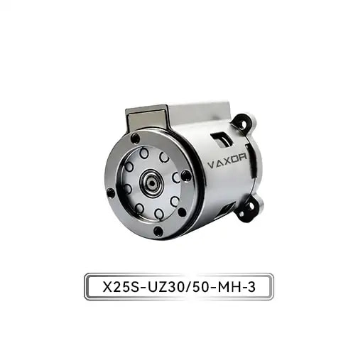
The Φ25mm Micro Joint Actuator is designed for compact robotic applications that require a combination of torque capacity, precise feedback, and integrated motion components. Its CAN FD communication interface provides an option for connecting the actuator to a compatible control architecture. To use that interface effectively, the network must be designed around the requirements of the complete robot rather than the actuator alone.
1. Define the Communication Requirements Before Selecting the Network Layout
A reliable CAN FD network starts with a clear understanding of what each joint needs to exchange with the main controller. Depending on the actuator and control architecture, this may include motion commands, position information, operating status, diagnostic data, or fault indications. The exact message content and update rates must be confirmed against the actuator's communication documentation.
Before drawing the network diagram, engineers should establish several basic requirements:
The number of actuator nodes and other devices connected to the bus.
The expected frequency of command and feedback messages.
The maximum acceptable delay between issuing a command and receiving relevant feedback.
The information needed for startup checks, fault detection, and recovery.
The communication behavior required when a joint becomes unavailable.
These requirements help determine whether the proposed network can support the intended motion-control tasks. For example, a small robotic arm with a limited number of joints may have different communication demands from a biomimetic mechanism with many independently controlled joints.
The X25 series uses CAN FD communication and is available under model designation X25S-UZ/BZ30/50-MH-3. Engineers should verify the exact communication parameters and supported operating modes for the selected configuration before integrating it into a controller.
2. Understand Where CAN FD Fits in Robotic Motion Control
CAN FD extends the original Controller Area Network by supporting a larger data field per frame and, when the network and devices are configured accordingly, a faster data phase than the nominal arbitration phase. This can improve the efficiency of transferring information, particularly when a control system needs to exchange larger amounts of status or diagnostic data.
However, CAN FD does not automatically guarantee lower control latency or better motion performance. Actual results depend on bus utilization, message priorities, frame lengths, controller configuration, wiring quality, and the scheduling strategy used by the robot's software.
In a multi-joint system, communication design should reflect the importance of each message. Time-sensitive motion commands and feedback may need higher priority than routine diagnostic information. If every message is transmitted without a clear priority strategy, lower-priority traffic can compete with information needed by the motion controller.
A practical message plan should specify:
Which messages are time-critical.
How frequently each message must be transmitted.
Which data can be sent less frequently or only when a value changes.
How the controller identifies missing or outdated feedback.
How diagnostic traffic is handled during normal operation and fault investigation.
These decisions should be documented before the control software is finalized. A clear message plan also makes it easier to identify whether a problem comes from network congestion, application scheduling, or actuator behavior.
3. Choose a Suitable Bus Topology and Wiring Arrangement
CAN networks generally use a linear bus with appropriate termination at the two physical ends. For CAN FD, the wiring arrangement becomes particularly important as the data-phase bit rate increases, because signal integrity is more sensitive to reflections, cable characteristics, and the physical layout.
In a robot with several joint modules, a linear backbone with short connections to individual nodes is usually a sensible starting point. Long branches, poorly placed termination resistors, and unnecessary connectors can introduce signal-quality problems. The actual topology must follow the requirements of the selected CAN FD transceivers, controller hardware, and intended data rate.
Engineers should review the following details during wiring design:
Use a cable suitable for the required CAN FD data rate and installation environment.
Keep branch connections short and avoid uncontrolled star-shaped layouts.
Install termination resistors at the physical ends of the bus as required by the network design.
Check connector pin assignments and ensure CAN high and CAN low are not reversed.
Route communication wiring with appropriate separation from noisy power circuits.
Provide suitable strain relief and protection where cables pass through moving structures.
The mechanical arrangement deserves special attention in compact robots. A joint may rotate repeatedly or sit inside a crowded housing, making cable routing and connector access difficult. The network should be checked across the complete range of motion, not just when the robot is stationary.
For the Φ25mm Micro Joint Actuator, the compact module size can help reduce mechanical packaging demands, but it does not remove the need for a properly designed communication harness. The wiring and connector requirements should be included in the joint's installation envelope from the beginning.
4. Calculate Bus Load and Message Timing
Once the number of nodes and message requirements are known, the next step is to estimate bus utilization. This helps engineers determine whether the network has enough capacity to support normal operation while leaving room for diagnostic messages and unexpected traffic.
A useful first approximation considers the number of frames transmitted per second, the size of each frame, and the time required to transmit it. CAN FD frame duration depends on the arbitration phase, data phase, frame format, payload length, bit-stuffing overhead, and other protocol details. Therefore, estimates based only on payload size can underestimate the actual bus load.
For a multi-joint robot, a message timing table can be used to organize the calculation.
| Message type | Design consideration |
|---|---|
| Motion commands | Define the required update interval and priority |
| Position or motion feedback | Set freshness requirements for closed-loop control |
| Operating status | Determine which values need frequent updates |
| Fault notifications | Establish how quickly critical faults must reach the controller |
| Diagnostic data | Avoid unnecessary traffic during time-sensitive operation |
The table should be populated using the actual message definitions and transmission rates supported by the selected hardware.
Engineers should also account for periods when several joints transmit at once. A network that performs well during a single-joint test may behave differently when all nodes report feedback at the same time. Staggering noncritical transmissions or adjusting message priorities may help, provided the changes remain compatible with the system's timing requirements.
The goal is not simply to keep average bus utilization low. The network must also deliver critical messages within the time limits required by the motion-control application.
5. Coordinate Position Feedback with Motion Commands
Communication quality affects how effectively the controller can use actuator feedback. If position data arrives late, is repeated unexpectedly, or is interpreted using an incorrect scaling or data format, the control system may make decisions based on an outdated view of the joint.
The X25 actuator specification lists an absolute magnetic encoder. This provides an absolute position-feedback capability, but the details of how position values are transmitted, initialized, and interpreted depend on the supported communication implementation.
During integration, engineers should verify the feedback data format, position units, valid ranges, update behavior, and any available status indicators. They should also confirm what happens during startup and whether the controller needs to complete an initialization or state-check procedure before issuing motion commands.
A useful test is to compare the commanded movement with the feedback received by the host controller. The test should check not only whether the values are plausible, but also whether they arrive at the expected time and correspond to the correct actuator.
For systems with several joints, each feedback message must be associated with the correct node. Incorrect node mapping or software configuration can produce confusing symptoms, including apparent position errors or unexpected coordinated motion.
These checks should be completed before the robot is tested under full operating loads.
6. Build Fault Detection into the Network Design
A robust communication system needs a defined response to missing or invalid data. Fault handling should not be added only after the first communication problem appears during testing.
Potential issues include a disconnected cable, a failed node, incorrect termination, electrical interference, excessive bus load, or a controller configuration error. The system should be able to detect relevant symptoms and distinguish between a temporary communication disturbance and a persistent fault where possible.
A practical fault-handling strategy should define the following behaviors:
Message timeout detection: Identify when expected messages have not arrived within the configured time window.
Data validation: Check whether received values fall within acceptable ranges and whether message status is valid.
Fault classification: Distinguish communication errors from actuator-reported faults and application-level problems.
Controlled response: Determine whether motion should continue, slow down, hold a safe state, or stop according to the system's risk assessment.
Recovery procedure: Specify how communication is re-established and what checks must pass before normal motion resumes.
The correct response depends on the robot's mechanics, operating environment, and safety requirements. A timeout should not automatically trigger the same action in every application. For example, an abrupt stop may itself create a hazard in some mechanisms, while continued movement without reliable feedback may be unacceptable in others.
Communication fault handling also should not be treated as a replacement for a properly engineered functional-safety system. Where personnel safety is involved, the system's safety functions must be designed and validated using the applicable risk assessment and standards.
7. Test the Network Under Realistic Operating Conditions
Bench testing is useful for confirming basic communication, but it cannot reveal every issue that may occur after the actuators, power wiring, and mechanical structures are assembled.
A staged validation process makes problems easier to isolate. Begin by checking one actuator and one controller, then add nodes gradually. Verify the physical layer and message exchange before introducing coordinated motion. Once the complete network is operating, repeat the tests under representative movement and load conditions.
A practical validation checklist includes:
Confirming the bus termination and physical wiring.
Checking communication at the intended nominal and data-phase bit rates.
Recording message timing and bus utilization under normal traffic.
Testing simultaneous feedback transmission from multiple nodes.
Monitoring communication errors during repeated movement.
Disconnecting or disabling a node under controlled test conditions to verify fault detection.
Confirming that recovery behavior matches the documented procedure.
For compact mechanisms, the test should include cable movement and vibration where relevant. A connection that works reliably with the robot stationary may become intermittent when the joint repeatedly changes direction.
Test records should identify the hardware configuration, firmware version, network settings, cable arrangement, and operating conditions. This information helps engineers reproduce faults and determine whether later changes have affected communication reliability.
8. Match Actuator Selection to the Complete Control Architecture
Communication is only one part of the actuator integration decision. Mechanical performance, electrical requirements, feedback capabilities, and network compatibility all need to work together.
The X25 series combines an axial-flux motor, a miniature cycloidal reducer, and a non-contact absolute magnetic encoder. Its listed specifications include a 12–18 V operating range, 30:1 and 50:1 gear ratios, continuous torque up to 1150 mNm, initial torque up to 1800 mNm, and a weight of 93–103 g. These figures should be checked against the exact selected configuration and its operating conditions.
When assessing the Φ25mm Micro Joint Actuator, engineering teams should verify both the physical and communication interfaces. The actuator's CAN FD support is useful only when the host controller, transceiver, wiring, network configuration, and application software are compatible. Likewise, torque and feedback specifications need to be evaluated against the required motion profile and load.
Founded in 2024 and headquartered in Suzhou, China, VAXOR develops micro joint actuators and ultra-micro coreless motors for robotics, medical devices, precision instruments, and intelligent equipment. Its multidisciplinary team brings together expertise in motor design, precision manufacturing, structural engineering, and robotics control, supporting development from prototype validation through pilot production and batch delivery.
For developers building collaborative robots or biomimetic joints, careful network planning can reduce debugging time and make system behavior easier to verify. Defining message timing, wiring rules, fault responses, and validation procedures early creates a stronger foundation for reliable integration.
The Φ25mm Micro Joint Actuator can be evaluated as part of this process when an application requires a compact joint module with CAN FD communication and integrated position feedback. The final decision should be based on verified interface documentation, realistic network testing, and the mechanical and control requirements of the complete robot.