 Store

 EN
 CN
 VI
 IT
 ES
 TH
 JA
 PT
 MS
 KO
 FR
 DE
 ID
As robots become smaller and more capable, integrating motion components into limited mechanical spaces has become a practical engineering challenge. Designers must fit actuators, wiring, sensors, and control electronics into compact assemblies without compromising movement, serviceability, or system reliability. This is particularly important for dexterous robotic hands, compact manipulators, medical devices, and precision instruments, where every millimeter of available space can affect the overall design.
A successful integration process starts with more than selecting an actuator that fits the mounting dimensions. Engineers also need to consider cable routing, power distribution, communication interfaces, load requirements, and access for assembly and maintenance. A compact joint module can simplify the mechanical layout, but only when its electrical and control requirements are considered at the same time.
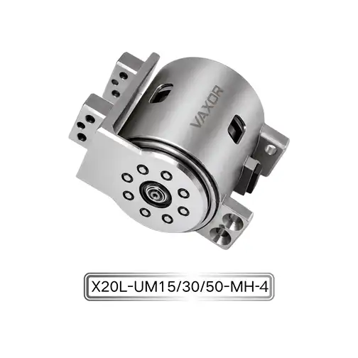
The Φ20mm Micro Joint Actuator from VAXOR provides an example of how these requirements can be addressed within a small motion system. Measuring just Φ20 mm × 20 mm, the X20 series combines a compact axial-flux motor architecture with a miniature cycloidal reduction mechanism, offering a practical starting point for designing space-constrained robotic joints.
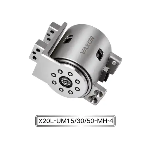
1. Start with the Complete Joint Envelope
When planning a compact robotic joint, the first step is to define the available installation space. Measuring only the actuator body is not enough. The design envelope should also account for mounting features, connectors, cable bends, neighboring components, and any movement required by the surrounding mechanism.
A module that fits perfectly into a CAD model may still be difficult to assemble if a connector is inaccessible or a cable must pass through a narrow moving gap. These problems are easier to address before the mechanical structure is finalized.
For a small robotic joint, engineers should check three dimensions during the initial layout:
Actuator envelope: Confirm the available diameter, axial length, and mounting clearances.
Electrical clearance: Reserve space for power and signal connections, including realistic cable bend radii.
Service access: Make sure connectors and fastening points remain accessible during assembly and maintenance.
The X20 measures Φ20 mm × 20 mm, giving designers a compact module to consider when developing space-efficient mechanisms. However, the final installation envelope should be verified against the selected configuration and its mounting and connection requirements rather than assuming that the actuator's nominal dimensions represent the complete installed space.
This approach is especially useful in multi-joint assemblies. When several actuators are positioned close together, a small interference at one joint can affect the layout of the entire mechanism.
2. Plan Cable Routing Before Finalizing the Mechanical Structure
Wiring is often one of the most overlooked parts of miniature actuator integration. In a compact robot, cables may need to pass through narrow structural channels, around rotating joints, or alongside other electrical components. Poor routing can create assembly difficulties, restrict movement, and introduce mechanical stress at connection points.
Power wiring and signal wiring should be considered separately during the layout stage. Power conductors must be selected for the expected current and voltage drop, while signal connections need routing that supports reliable communication and minimizes interference risks.
For multi-axis robots, cable routing also needs to accommodate movement. Engineers should check whether wires twist, stretch, rub against surrounding surfaces, or become trapped when the mechanism reaches its operating limits. Repeated movement can gradually damage insulation or connectors even when the initial assembly appears correct.
A practical cable-routing review should include the following checks:
Identify a defined path for each power and communication connection.
Keep cables clear of gears, rotating shafts, and moving structural parts.
Avoid sharp bends and excessive tension at connector interfaces.
Provide strain relief where cables enter or leave the joint assembly.
Verify clearance across the complete range of motion, not just the neutral position.
For compact systems using the X20 micro joint actuator, cable routing should be evaluated alongside the selected voltage and control architecture. The small actuator envelope can help reduce mechanical packaging demands, but the surrounding design still needs sufficient room for dependable electrical connections.
3. Match the Power Supply to the System Architecture
The supply voltage affects more than the connection between an actuator and its power source. It also influences current requirements, conductor sizing, power distribution, and the design of the wider electrical system.
The X20 series supports 12 V, 24 V, and 48 V configurations. This provides options for different system architectures, but engineers should confirm the rated voltage of the exact model before selecting the power supply or designing the distribution circuit.
For a given electrical power level, a higher supply voltage generally allows lower current, which can help reduce resistive losses and simplify conductor sizing. However, the actual benefit depends on the actuator's electrical characteristics, operating load, driver design, and system-level constraints. Voltage selection should therefore be based on the complete motion system rather than one component in isolation.
When several joints share a power source, the electrical design should account for simultaneous operation. Multiple actuators accelerating at the same time can create different power demands from those observed during a single-joint bench test. Engineers should evaluate the expected operating cycle, supply capacity, voltage drop, protection strategy, and available current under realistic conditions.
Before completing the wiring diagram, verify the following:
The supply voltage matches the selected actuator configuration.
Connectors and conductors meet the electrical requirements.
The power supply can support the expected combined load.
Protection and grounding arrangements suit the system design.
Startup and simultaneous motion have been tested under representative conditions.
These checks help prevent power distribution from becoming a limitation after the mechanical assembly has already been completed.
4. Integrate SPI Communication into the Control Design
A compact joint requires a clear control architecture as well as a suitable mechanical arrangement. The communication interface determines how the actuator connects to the host controller and how the joint fits into the wider motion-control system.
The X20 specification lists SPI communication. Engineers integrating this interface should confirm the electrical signaling requirements, pin assignments, timing parameters, and communication protocol supported by the selected actuator configuration. These details should be obtained from the relevant technical documentation before software implementation begins.
SPI can be useful in embedded systems where a controller communicates with peripheral devices through a synchronous serial interface. However, the suitability of an SPI-based arrangement depends on the system topology, wiring length, controller resources, and implementation requirements. It should not be assumed that every multi-axis architecture can use the same wiring arrangement without additional planning.
During integration, developers should define how the host controller addresses and manages each joint, how communication errors are detected, and what the system does when valid data is unavailable. These decisions become particularly important when multiple actuators operate as part of one coordinated mechanism.
A structured integration test can include:
Confirming the interface pinout and electrical compatibility.
Verifying communication timing and data interpretation.
Testing command and feedback behavior under normal operation.
Checking the response to interrupted communication or invalid data.
Repeating the tests after the final cable harness and mechanical assembly are installed.
For teams developing embedded robotic platforms, VAXOR combines expertise in motor design, precision manufacturing, structural engineering, and robotics control. This multidisciplinary background is relevant to compact drive development because successful integration depends on coordination between mechanical, electrical, and control engineering rather than treating each discipline separately.
5. Check Torque Requirements Against Real Operating Conditions
Compact packaging should never be the only criterion for selecting a joint module. The actuator must also deliver sufficient torque for the intended movement, including acceleration, deceleration, friction, and changes in external load.
The X20 series specifies continuous torque of up to 450 mNm and initial torque of up to 800 mNm. These are maximum stated values, not guarantees that every model or operating condition will deliver the same performance. Engineers should confirm the applicable specifications for the selected model and distinguish between continuous operating capability and short-duration or initial torque.
A useful evaluation begins with the mechanical load. For a rotating joint, the required torque depends on factors such as the applied force, its distance from the rotation axis, the mass distribution of moving parts, and the desired angular acceleration. Gravity and external contact forces may also influence the load throughout the motion cycle.
For example, a compact gripper joint that moves a lightweight finger through a short range may have very different requirements from a joint that repeatedly accelerates a longer link. Both assemblies may have similar external dimensions, but their torque demand and operating duty cycles can differ considerably.
Engineers should evaluate the following before confirming the actuator choice:
Required torque throughout the complete motion profile.
Peak demand during acceleration, contact, and changes in direction.
Continuous demand over the expected duty cycle.
Mechanical transmission losses and load variation.
Thermal behavior during representative operation.
The Φ20mm Micro Joint Actuator can then be assessed against these requirements, rather than selected solely because its diameter fits the available space. Where application data is incomplete, testing under representative loads is preferable to relying on nominal torque figures alone.
6. Consider Gear Ratio and Motion Requirements Together
The X20 series is available with gear ratios of 15:1, 30:1, and 50:1. The choice should reflect the application's balance between output torque, speed, responsiveness, and control requirements.
A higher reduction ratio generally increases the torque multiplication available at the output while reducing output speed for a given motor speed. Actual performance also depends on transmission efficiency, motor characteristics, and the actuator's operating limits. A larger ratio should not automatically be treated as the best option for every joint.
For a fast-moving mechanism, the design team may prioritize output speed and responsive movement. A joint that handles a heavier load or requires greater torque multiplication may lead to a different selection. In both cases, the complete motion profile matters more than a single target value.
The selected ratio should be evaluated alongside the required range of motion, cycle time, expected load, and control strategy. Engineers should also verify any model-specific speed and torque curves rather than extrapolating performance from the ratio alone.
Documenting these requirements early helps prevent late-stage changes to the actuator, mounting structure, or control parameters.
7. Reserve Space for Testing and Maintenance
A compact mechanism should remain practical to build and maintain after the first prototype is completed. When actuator modules are packed tightly together, it can become difficult to reach connectors, replace a damaged cable, inspect mounting hardware, or isolate a fault.
Design reviews should therefore include assembly and maintenance scenarios. Consider whether a joint can be removed without dismantling unrelated components, whether fastening tools can reach the mounting points, and whether cables can be disconnected without placing stress on adjacent connections.
The same principle applies to validation. A prototype should be tested in stages, beginning with individual actuator operation and progressing to the fully integrated mechanism.
A sensible sequence includes checking mechanical clearance, verifying power and communication, testing motion without the full external load, and then evaluating the system under representative operating conditions. Temperature, current consumption, positioning behavior, and cable movement can be monitored where the required instrumentation is available.
Any unexpected vibration, communication interruption, excessive heating, or mechanical interference should be investigated before the design moves to a larger production run. Recording the test conditions and configuration also makes results easier to reproduce when the hardware or software changes.
8. Choose a Joint Module with Integration in Mind
The most suitable actuator is not necessarily the smallest component or the one with the highest headline torque. It is the module that satisfies the application's mechanical, electrical, and control requirements while fitting the available space and remaining practical to manufacture and service.
The X20 series combines a Φ20 mm × 20 mm form factor with an axial-flux motor architecture designed to achieve over 30% higher torque density than conventional designs, according to the product specifications. Its listed features include 12 V, 24 V, and 48 V options, 15:1, 30:1, and 50:1 gear ratios, an absolute magnetic encoder, SPI communication, and a weight range of 37.2–41.6 g. Exact performance and configuration details should be confirmed against the selected model.
Founded in 2024 and headquartered in Suzhou, China, VAXOR develops micro joint actuators and ultra-micro coreless motors for robotics, medical devices, precision instruments, and intelligent equipment. Its development approach integrates axial-flux motors, PCB/FPCB winding, electromagnetic optimization, and miniature reduction mechanisms, with a focus on translating engineering development into scalable production.
For product development teams, the value of a compact actuator lies in how well it works within the complete assembly. Evaluating the mechanical envelope, wiring path, supply architecture, communication interface, torque demand, and maintenance requirements together can reduce integration problems and support more predictable prototype development.
When these factors are addressed early, the X20 micro joint actuator becomes a candidate for compact robotic mechanisms where space efficiency must be balanced with practical electrical integration and controlled motion. A clear set of application requirements and validation tests provides the foundation for deciding whether the selected configuration is appropriate for the final design.