 Store

 EN
 CN
 VI
 IT
 ES
 TH
 JA
 PT
 MS
 KO
 FR
 DE
 ID
As miniature mechanisms become more capable, their motors must deliver enough torque without taking up excessive space or adding unnecessary weight. In a compact device, even a small increase in mechanical resistance can affect movement, response, and operating consistency. Selecting a motor therefore requires more than checking its maximum speed or external dimensions. Engineers need to understand how much torque it can provide under normal operating conditions and whether that output is suitable for the complete mechanism.
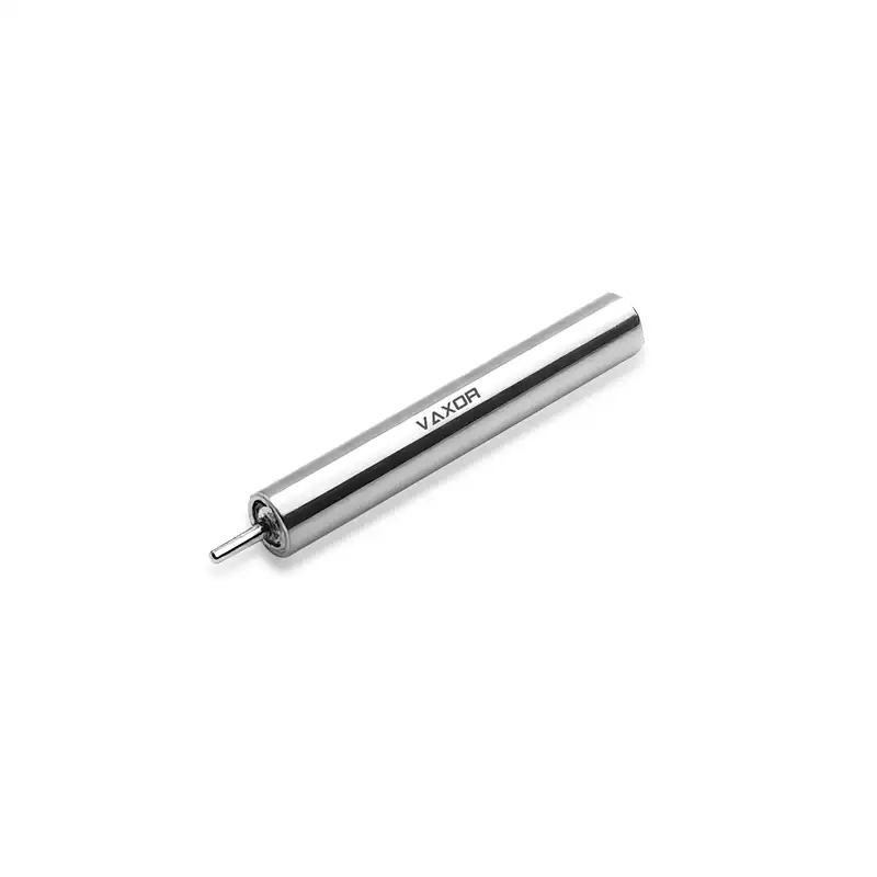
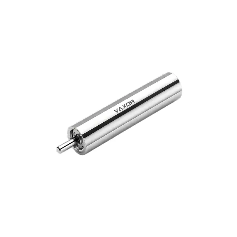
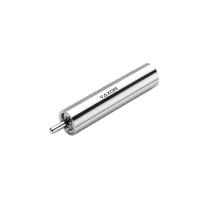
The φ6mm Ultra-micro Brushless Coreless Motor is designed for demanding miniature applications where compact dimensions must be combined with practical torque output and drive stability. Its nominal torque is 0.49 mNm, supported by a 0.98 mNm stalling torque and a torque constant of 1.05 mNm/A. These specifications provide useful reference points when evaluating its potential role in compact motion systems.
What Does 0.49 mNm Rated Torque Mean?
Rated torque describes the torque a motor is specified to deliver under its nominal operating conditions. For a miniature drive, this value is particularly important because the available mechanical output is limited by the motor's size, electromagnetic design, thermal behavior, and operating conditions.
The G06P-VW00-QZ-1 model has a nominal torque of 0.49 mNm. This figure should be considered when estimating whether the motor can overcome the resistance of a connected mechanism during normal operation. The required torque may come from several sources, including friction in bearings, resistance in gears, the inertia of moving components, and external forces acting on the mechanism.
A motor should not be selected simply because its rated torque appears close to the estimated load. The actual application may introduce additional resistance during startup, changes in movement direction, or periods of acceleration. Engineers should account for these conditions and establish an appropriate operating margin.
For example, a compact positioning mechanism may require relatively little torque once it reaches a steady speed, but a higher torque demand when starting from rest. Evaluating both conditions helps determine whether the motor can perform consistently rather than only under an ideal, stable load.
Rated Torque and Stall Torque Serve Different Purposes
The rated torque of this 6mm motor is 0.49 mNm, while its stalling torque is 0.98 mNm. Although both values describe torque output, they represent different operating conditions and should not be treated as interchangeable.
Rated torque is the more relevant reference when evaluating normal operation. Stall torque describes the torque associated with a stalled motor condition. It indicates a higher torque capability under that condition, but it does not mean the motor should be operated continuously at this level.
A stalled or heavily overloaded motor can draw excessive current and generate heat. In a compact assembly, heat dissipation may be limited by the surrounding housing, nearby electronic components, and the available airflow. Repeatedly approaching stall conditions can therefore affect operating reliability and service life.
When designing a mechanism around the 6mm brushless coreless motor, engineers should compare the expected working load with the nominal torque rather than using stall torque as the target operating point. Stall torque is useful for understanding the motor's output boundary, while rated torque provides a more appropriate basis for normal load evaluation.
Using the Torque Constant to Estimate Current Demand
Torque output is closely related to motor current. The torque constant indicates how much torque is generated per unit of current under the specified motor characteristics.
For model G06P-VW00-QZ-1, the torque constant is 1.05 mNm/A. This provides an initial reference for estimating the current associated with a required torque. In an idealized calculation, the relationship can be expressed as:
Torque = Torque Constant × Current
Rearranging the relationship gives:
Current = Required Torque ÷ Torque Constant
This calculation helps engineers make an initial estimate of the current needed to produce a target torque. For example, a design requiring torque close to the motor's nominal output can use the 1.05 mNm/A value as a starting point for evaluating the drive electronics.
However, this estimate should not be treated as a complete prediction of actual power consumption. Real operating conditions involve electrical and mechanical losses, winding resistance, temperature changes, and the characteristics of the motor controller. The final current requirement should be verified through the motor's technical documentation and application testing.
Understanding this relationship also helps when selecting a driver. The controller must support the required current and respond appropriately to changes in load. A motor with suitable torque specifications may still perform poorly if the driver cannot provide stable current control.
How Speed and Load Affect Available Output
The G06P-VW00-QZ-1 operates at a rated voltage of 12 V, with a no-load speed of 63,000 rpm and a nominal speed of 45,000 rpm. These two speed ratings describe different operating conditions.
No-load speed represents motor rotation without an external mechanical load. Once the motor is connected to a mechanism, resistance affects its operating speed. The nominal speed provides a reference under the specified nominal operating condition and should not be confused with the no-load figure.
This distinction matters when designing a miniature mechanism. A motor may appear to provide sufficient speed when evaluated using its no-load rating, but the connected load changes the actual operating point. Friction, transmission resistance, and the inertia of moving parts all influence the speed and torque required during operation.
Engineers should therefore evaluate speed and torque together. A design that focuses only on high rotational speed may overlook the torque needed to move the connected components. Conversely, a mechanism that requires substantial torque may need to operate at a lower speed than its initial design target.
The φ6mm Ultra-micro Brushless Coreless Motor combines a 45,000 rpm nominal speed with 0.49 mNm nominal torque, giving designers two important parameters for assessing its suitability in high-speed miniature drive applications.
Evaluating Mechanical Loads Before Motor Selection
Before integrating a micro motor, it is useful to break down the mechanical load into its main components. This makes it easier to identify where torque demand originates and whether the motor has sufficient capacity.
Several factors deserve attention:
Friction: Bearing contact, sliding surfaces, and gear engagement create resistance that the motor must overcome.
Inertia: Moving components require additional torque during acceleration and deceleration.
Transmission losses: Gears, couplings, and other mechanical interfaces reduce the torque delivered to the final load.
External resistance: The mechanism may experience changing forces depending on its working environment.
Assembly variation: Differences in alignment, clearance, and component tolerances can affect the required driving torque.
These factors should be considered together rather than evaluated separately. For instance, a small gear mechanism may have a relatively low steady-state load but experience higher resistance during startup because of friction and component inertia.
A practical approach is to estimate the torque demand at the motor shaft, account for transmission efficiency where applicable, and compare the result with the motor's nominal torque. Prototype testing can then confirm whether the calculated operating point reflects actual conditions.
Why Motor Weight and Dimensions Matter
Torque is only one part of a miniature motor selection decision. The motor must also fit the available installation space and remain within the weight budget of the complete device.
The G06P-VW00-QZ-1 weighs 3.75 g and uses a 6mm motor format. This compact footprint can be useful in equipment where larger drive components would restrict the mechanical layout or increase the load carried by a moving assembly.
In small robotic mechanisms, for example, motor weight can influence the inertia of a moving joint or end-effector. In precision instruments and intelligent equipment, installation space may be shared with sensors, wiring, control boards, and structural supports. The motor's dimensions and mounting arrangement therefore need to be considered as part of the overall system design.
A suitable motor is not necessarily the one with the highest torque specification. It is the one that meets the actual load requirement while fitting the device's dimensional, electrical, thermal, and mechanical constraints.
From Motor Specifications to Application Validation
A specification sheet provides the starting point for motor selection, but it cannot describe every condition in a finished device. Before finalizing a design, engineers should test the motor with the intended load, driver, mounting structure, and transmission components.
Useful validation steps include measuring startup behavior, observing speed under representative loads, checking current consumption, and monitoring temperature during operation. Repeated tests can also help identify variations caused by assembly tolerances or changes in mechanical resistance.
For demanding miniature applications, this process is especially important because limited installation space can make thermal management and maintenance more difficult. The motor should be evaluated as part of the complete drive assembly rather than as an isolated component.
VAXOR, founded in 2024 and headquartered in Suzhou, China, develops micro joint actuators and ultra-micro coreless motors for robotics, medical devices, precision instruments, and intelligent equipment. Its technical roadmap combines axial-flux motor technology, PCB/FPCB winding, optimized electromagnetic design, and miniature reduction mechanisms.
Supported by a multidisciplinary team covering motor design, precision manufacturing, structural engineering, and robotics control, VAXOR works across prototype validation, pilot production, and batch delivery. This engineering approach supports the development of compact drive solutions that balance performance requirements with practical manufacturing considerations.
Matching Torque Capacity to the Real Application
The 0.49 mNm nominal torque of the φ6mm Ultra-micro Brushless Coreless Motor provides a clear starting point for evaluating its output capacity. Combined with a 0.98 mNm stalling torque, 1.05 mNm/A torque constant, 12 V rated voltage, and 3.75 g weight, the G06P-VW00-QZ-1 offers several useful reference parameters for miniature drive design.
The key is to interpret these figures in the context of the actual mechanism. Engineers should estimate the working load, consider startup and acceleration requirements, assess current demand, and verify performance under representative operating conditions. By connecting motor specifications with real mechanical requirements, designers can make more reliable selection decisions and avoid sizing a drive system around a single headline parameter.
For applications that require compact dimensions alongside practical torque output, the 6mm Ultra-micro Brushless Coreless Motor offers a useful basis for developing and validating high-performance miniature motion systems.