 Store

 EN
 CN
 VI
 IT
 ES
 TH
 JA
 PT
 MS
 KO
 FR
 DE
 ID
Designing an ultra-micro motor is not simply a matter of making every component smaller. As the available space decreases, engineers must work with tighter structural constraints, limited material allowances, and increasingly demanding performance requirements. A small change in winding layout, magnetic circuit geometry, or assembly tolerance can influence the motor's output, weight, and manufacturing complexity.
For manufacturers developing motors for UAVs, wearable devices, and compact intelligent equipment, the challenge is to achieve a practical balance between performance and production feasibility. AI-assisted design offers another way to approach this challenge by helping engineers analyze design variables, compare alternative configurations, and identify opportunities for improvement.
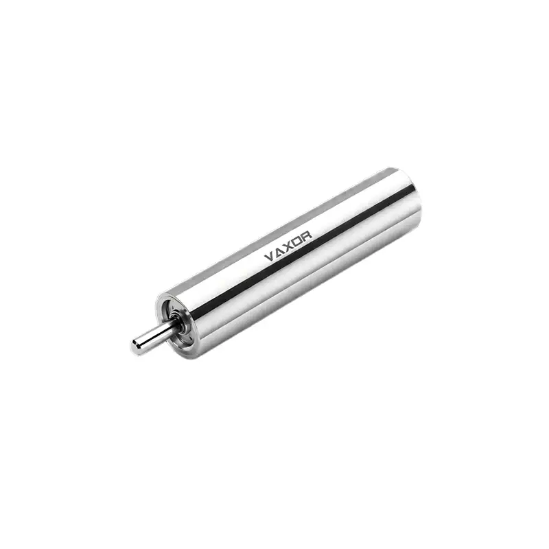
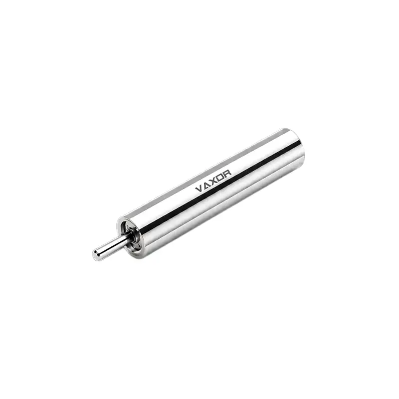
The φ5mm Ultra-micro Brushless Coreless Motor is developed around this balance. Combining FPCB winding technology with AI-optimized design, it targets applications where compact dimensions, dependable motion performance, and manufacturability are all important. Its G05P-VW00-QZ-1 model provides a useful example of how motor specifications can be considered together rather than optimized in isolation.
Why Ultra-Micro Motor Design Requires Multiple Trade-Offs
In a conventional motor design, engineers may have more room to adjust the winding structure, magnetic components, and housing dimensions. In a motor with a diameter of only 5 mm, these design options become much more restricted.
Increasing the amount of winding material, for example, may affect the available internal space and the arrangement of other components. Changing the magnetic circuit may influence torque generation, while modifying the mechanical structure can affect weight, assembly requirements, and production consistency.
These variables are interconnected. A design that performs well in a simulation may still be difficult to manufacture consistently. Similarly, a structure that is easy to assemble may not provide the desired torque or speed characteristics.
The design process therefore needs to consider several objectives at the same time:
Achieving the required torque and rotational speed.
Keeping the motor within strict dimensional and weight limits.
Managing electrical and thermal behavior under the intended operating conditions.
Maintaining dimensional and performance consistency between production batches.
Avoiding unnecessary manufacturing steps and material complexity.
This is where AI-assisted optimization can support engineering decisions. Instead of relying entirely on sequential manual adjustments, engineers can use computational analysis to explore multiple design combinations and identify promising configurations for further validation.
How AI-Optimized Design Supports Motor Development
AI does not replace electromagnetic engineering or physical testing. Its value lies in helping engineers analyze complex relationships between design variables and narrow down the configurations that deserve further investigation.
For an ultra-micro brushless motor, the optimization process may involve several areas.
Electromagnetic structure analysis
The magnetic circuit, winding arrangement, and available internal space influence the motor's torque characteristics. Simulation and data-assisted analysis can help engineers compare different structural configurations and evaluate how design changes may affect electromagnetic performance.
Winding layout evaluation
Winding design is particularly important when the available space is extremely limited. Engineers need to consider conductor arrangement, winding utilization, electrical characteristics, and the practical requirements of the manufacturing process. AI-assisted analysis can help compare potential layouts, while prototype testing determines whether the selected configuration performs as expected.
Weight and structural optimization
Reducing weight should not compromise the mechanical integrity or reliability of the motor. Design analysis can help identify areas where material distribution or component geometry may be adjusted without introducing unnecessary structural risks.
Manufacturing-oriented design
A motor design must be suitable for actual production, not just theoretical performance. Evaluating assembly tolerances, process repeatability, material utilization, and inspection requirements during the design stage can help reduce problems when moving from prototypes to batch manufacturing.
The important point is that AI-assisted optimization should be connected to engineering validation. Simulation results need to be checked against physical prototypes, measured performance, and manufacturing feedback before design decisions are finalized.
FPCB Winding and Its Role in a 5mm Motor
Winding technology has a direct influence on how effectively the limited internal space of a miniature motor is used. In a compact structure, conventional winding arrangements may face practical challenges related to conductor placement, assembly access, and dimensional consistency.
FPCB winding technology offers an alternative approach by using a patterned flexible printed circuit structure for the winding arrangement. It can support more controlled conductor layouts and provide a manufacturing route suited to compact motor architectures.
However, the benefits of FPCB winding depend on the complete motor design. Engineers still need to evaluate electrical resistance, current capacity, thermal behavior, connection reliability, and the integration of the winding structure with the magnetic circuit.
For the φ5mm Ultra-micro Brushless Coreless Motor, FPCB winding works alongside AI-optimized design. The two approaches address different but related engineering challenges: winding technology influences how the motor's electrical structure is implemented, while design optimization helps evaluate how that structure interacts with the rest of the motor.
This combination is relevant when a product must satisfy both performance requirements and manufacturing constraints. It also makes process validation important, because the final result depends on the repeatability of winding fabrication, assembly, and electrical testing.
Reading the Performance Parameters as a Complete Set
The G05P-VW00-QZ-1 model illustrates why motor specifications should be evaluated together. Its key parameters are:
Model: G05P-VW00-QZ-1
Rated voltage: 6 V
No-load speed: 55,000 rpm
Nominal speed: 30,000 rpm
Nominal torque: 0.40 mNm
Stalling torque: 0.80 mNm
Torque constant: 0.65 mNm/A
Weight: 2.6 g
Each parameter describes a different aspect of the motor's operating capability.
The 55,000 rpm no-load speed indicates the motor's rotational speed under the specified no-load test condition. It should not be interpreted as the speed that will necessarily be achieved in an assembled device. Once an external mechanism is connected, friction, transmission losses, and applied torque affect the actual operating speed.
The nominal speed of 30,000 rpm is associated with a nominal torque of 0.40 mNm. These two values provide a more practical reference for evaluating the motor under its specified working condition.
The 0.80 mNm stalling torque represents a stationary rotor condition under the specified test conditions. It is not a recommended continuous operating torque. Sustained operation near stall can cause high current and thermal stress, so application design should be based on the motor's appropriate operating range.
The torque constant of 0.65 mNm/A helps engineers understand the relationship between current and generated electromagnetic torque. It can support preliminary driver selection and current-demand analysis, although the actual electrical design must also account for winding resistance, supply voltage, driver limitations, and temperature.
Taken together, these specifications help engineers determine whether the motor's output characteristics are suitable for a particular mechanism. They also provide measurable references for prototype testing and production quality checks.
Balancing Torque, Weight, and Manufacturing Cost
The relationship between torque, weight, and manufacturing cost is not always straightforward. Improving one aspect may create additional requirements elsewhere in the design.
For example, increasing torque capability may require changes to the electromagnetic structure or winding configuration. These changes can affect material usage, internal dimensions, thermal behavior, and assembly processes. Reducing weight may require a different structural arrangement, but the revised design must still meet mechanical and production requirements.
Manufacturing cost is influenced by more than the amount of material used. It can also depend on process complexity, equipment requirements, assembly time, inspection procedures, yield, and production volume.
A practical optimization process should therefore evaluate the following factors:
Performance requirements: Define the actual speed, torque, voltage, and duty cycle required by the application. Avoid optimizing for maximum speed or peak torque when those values are not needed in normal operation.
Material and process selection: Consider whether the selected winding and structural materials can meet performance requirements while remaining suitable for repeatable manufacturing.
Assembly complexity: Review how many operations are required to assemble the motor and whether the design allows stable positioning and connection of miniature components.
Quality control: Identify the parameters that need to be checked during production, such as electrical characteristics, rotational speed, dimensional accuracy, and functional performance.
Production scalability: Confirm that the manufacturing process used for prototypes can be adapted to pilot production and larger batches without unacceptable variation.
For the 5mm ultra-micro brushless coreless motor, this integrated approach is important because the product is intended to balance performance, cost, and manufacturability rather than maximize a single specification at the expense of the others.
Application Considerations for UAVs and Wearable Devices
UAVs and wearable devices have different operating requirements, but both place considerable demands on miniature drive components.
In UAV applications, motor selection may involve rotational speed, available torque, system weight, power consumption, and the mechanical characteristics of the driven mechanism. The motor must be evaluated within the complete assembly, including its controller, mounting structure, transmission components, and power source. A high no-load speed alone does not establish suitability for a particular UAV function.
Wearable devices introduce another set of constraints. Available space is limited, and the motor may operate within a compact enclosure alongside batteries, sensors, and electronic control components. Engineers need to consider weight distribution, operating noise, heat transfer, duty cycle, and the movement required by the device.
The φ5mm Ultra-micro Brushless Coreless Motor is designed for these kinds of space-constrained applications. Its 5 mm diameter and 2.6 g weight provide a compact starting point for system integration. Whether it is suitable for a specific device depends on the required torque, speed, operating duration, and mechanical arrangement.
From Design Optimization to Repeatable Production
An optimized motor design only becomes commercially useful when it can be manufactured consistently. This requires coordination between research and development, process engineering, prototype validation, and production quality control.
Founded in 2024 and headquartered in Suzhou, China, VAXOR develops micro joint actuators and ultra-micro coreless motors for robotics, medical devices, precision instruments, and intelligent equipment.
Its multidisciplinary team brings together expertise in motor design, precision manufacturing, structural design, robotics control, and intelligent manufacturing. This combination supports development work across the complete engineering process, from initial prototypes and performance validation to pilot production and batch delivery.
VAXOR's technology roadmap focuses on compact size, high performance, and scalable production. Its technical approach integrates axial-flux motor technology, PCB/FPCB winding, optimized electromagnetic design, and miniature reduction mechanisms to develop compact motion solutions with high power density, fast response, and consistent performance.
For customers evaluating a miniature motor, this engineering capability is relevant beyond the initial product specification. The ability to assess application requirements, validate prototypes, refine manufacturing processes, and support production scaling can help bridge the gap between a promising design and a practical drive component.
Conclusion
AI-optimized motor design is most valuable when it helps engineers make better decisions across the entire development process. For ultra-micro motors, torque, weight, electrical performance, structural dimensions, and manufacturing requirements cannot be treated as independent targets.
By combining FPCB winding technology with AI-assisted design analysis and physical validation, manufacturers can evaluate different design options while keeping production feasibility in view.
The φ5mm Ultra-micro Brushless Coreless Motor, model G05P-VW00-QZ-1, brings together a 6 V rated voltage, 30,000 rpm nominal speed, 0.40 mNm nominal torque, and 2.6 g weight in a compact motor platform. For UAVs, wearables, and other miniature applications, its suitability should be assessed against the actual load profile and system requirements.
With its focus on motor innovation, engineering implementation, and scalable manufacturing, VAXOR continues to develop compact drive technologies for applications where performance and practical production must work together.