 Store

 EN
 CN
 VI
 IT
 ES
 TH
 JA
 PT
 MS
 KO
 FR
 DE
 ID
In miniature drive systems, a motor's maximum speed can look impressive on a specification sheet, but it does not necessarily represent the speed that a device will achieve during normal operation. Once a motor is connected to a transmission mechanism or an actual working load, its rotational speed changes according to the torque required by the application. Understanding this relationship is essential when designing compact equipment where limited installation space leaves little room for oversized drive components.
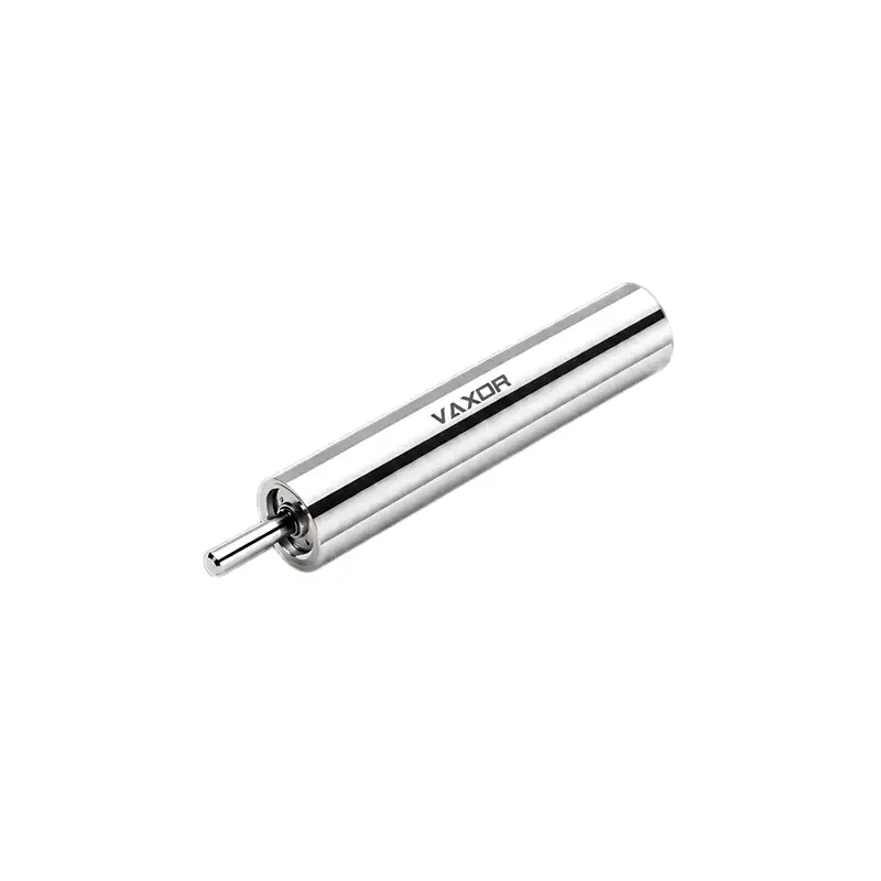
The φ4mm Ultra-micro Brushless Coreless Motor illustrates this difference clearly. Its specified no-load speed reaches 55,000 rpm, while its nominal speed is 30,000 rpm. Both figures describe important aspects of motor performance, but they represent different operating conditions. For engineers developing medical devices, precision instruments, and advanced miniature equipment, the key is to understand what happens between these two points and how to select a suitable operating range.
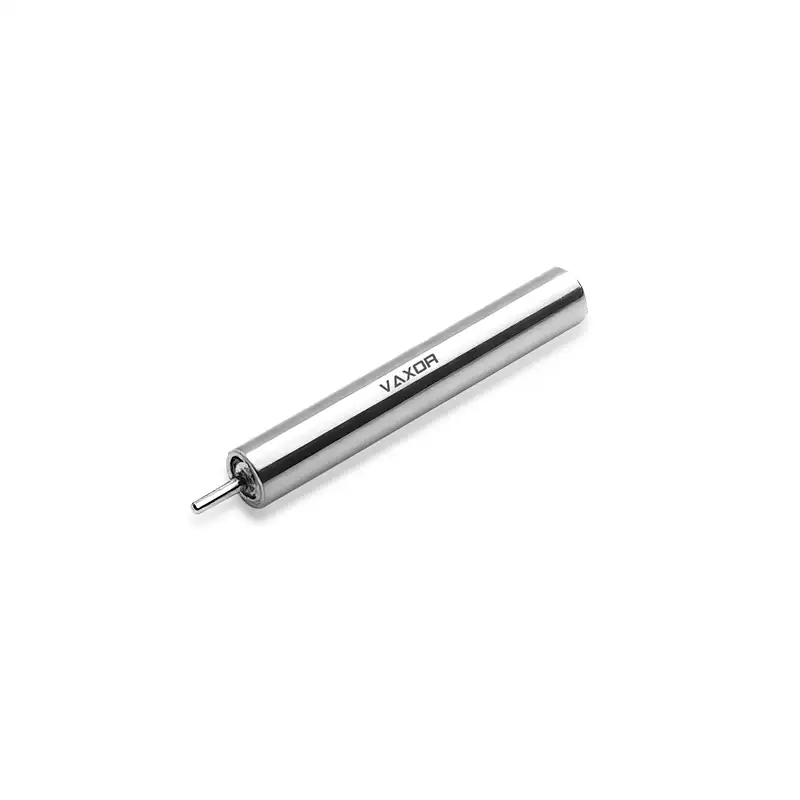
No-Load Speed and Nominal Speed Describe Different Conditions
No-load speed is the rotational speed measured when the motor runs without an external mechanical load on its output shaft. Under this condition, the motor mainly overcomes its own internal losses, including friction and other sources of resistance. Because the required output torque is relatively low, the motor can reach a high rotational speed.
For the G04P-VW00-QZ-1 model, the specified no-load speed is 55,000 rpm at 6 V. This value indicates its high-speed capability under the stated no-load test condition. However, it should not be treated as the expected speed after the motor is installed in a working device.
Nominal speed represents a specified operating condition under load. For this motor, the nominal speed is 30,000 rpm, accompanied by a nominal torque of 0.38 mNm. This gives engineers a more practical reference when evaluating the motor for applications that require continuous or regular mechanical output.
The difference between 55,000 rpm and 30,000 rpm is therefore not evidence of poor performance. It reflects the additional torque required to drive an external load. As the motor supplies mechanical output, its operating point moves away from the no-load condition.
How Applied Load Changes Motor Speed
A motor's speed and torque are closely related. When an external mechanism requires more torque, the motor must produce a stronger electromagnetic response to maintain rotation. Under a fixed supply condition, this generally results in a lower operating speed.
Several factors determine the load experienced by a miniature motor:
Mechanical friction: Bearings, shaft supports, seals, and contacting components introduce resistance that the motor must overcome.
Transmission losses: Gears, couplings, and other power-transfer components consume part of the motor's available output.
Driven mechanism resistance: The actual device may require different torque levels during startup, acceleration, and steady operation.
Load variation: Changes in contact force, material resistance, or movement direction can cause the required torque to fluctuate.
For example, a compact instrument may require relatively little torque while moving freely but encounter greater resistance when a mechanical element engages with a working component. In this situation, the motor's speed may decrease as the required torque increases.
This is why selecting a motor based only on its no-load speed can lead to an unsuitable design. Engineers need to estimate the complete load profile and determine whether the motor can provide the required speed and torque at the same time.
Understanding the Torque Ratings of a 4mm Motor
The torque specifications provide another perspective on the motor's operating capability.
The G04P-VW00-QZ-1 model has a nominal torque of 0.38 mNm and a stalling torque of 0.76 mNm. These values should not be interpreted as interchangeable operating targets.
Nominal torque is the more relevant reference when assessing the motor's specified working performance. It helps engineers evaluate whether the motor can drive the intended mechanism under its expected operating conditions.
Stalling torque refers to the torque associated with a stationary rotor under the specified test condition. It represents a limit condition rather than a recommended continuous operating point. A motor held near stall can experience substantial current and heat generation, potentially placing stress on its winding and drive electronics.
For practical design, the required load torque should be evaluated against the motor's rated operating characteristics, with appropriate consideration for startup resistance, acceleration, transmission losses, and variations in the application.
The 4mm brushless coreless motor provides a useful example of why torque and speed need to be considered together. Its 0.38 mNm nominal torque is associated with a nominal speed of 30,000 rpm, offering a more meaningful reference for evaluating an actual drive requirement than either parameter viewed independently.
Using the Torque Constant to Evaluate Drive Requirements
Torque constant is another important specification when matching a motor to its electronic drive system. The G04P-VW00-QZ-1 has a torque constant of 0.82 mNm/A.
In simplified terms, torque constant describes the relationship between motor current and the electromagnetic torque generated by the motor. It allows engineers to estimate the current required for a particular torque demand, subject to the motor's operating conditions and the manufacturer's specified test method.
For example, a design team can use the torque constant as an initial reference when evaluating whether the selected driver has sufficient current capability. If the application requires a certain output torque, the estimated motor current can help guide driver selection and electrical design.
However, the torque constant alone does not determine the final operating speed. Engineers must also consider winding resistance, supply voltage, driver limitations, temperature rise, and the mechanical load. A complete assessment should use the motor's performance curve and detailed electrical specifications whenever available.
For a 6 V miniature drive system, the power supply and driver should be selected to support the intended operating range rather than simply accommodate the motor's maximum no-load speed.
Why Mechanical Integration Matters at 30,000 RPM
At rotational speeds of tens of thousands of revolutions per minute, the surrounding mechanical structure becomes an important part of the drive system. Even a small amount of misalignment or unnecessary friction can affect operating efficiency and stability.
For a motor with a diameter of only 4 mm, installation constraints can make these issues more difficult to manage. Engineers should pay attention to several practical details:
Shaft alignment: The motor shaft and driven component should be properly aligned. Misalignment can introduce additional radial loads, friction, and vibration.
Coupling design: The connection between the motor and the driven mechanism should transfer torque without introducing excessive resistance or imbalance.
Support structure: Mounting and shaft-support arrangements should be suitable for the intended speed range and mechanical loading conditions.
Thermal management: High-speed operation and sustained loading generate heat. The surrounding structure should not prevent appropriate heat dissipation.
Dynamic balance: Rotating components should be designed and assembled to minimize unnecessary vibration, particularly when the device operates at high rotational speeds.
These considerations are especially relevant in medical devices and precision instruments, where limited space and strict operating requirements make mechanical integration just as important as the motor's electrical specifications.
Matching the Operating Point to the Application
A suitable motor selection begins with the actual requirements of the driven mechanism. Instead of asking only how fast a motor can rotate, engineers should identify the required operating speed, torque, duty cycle, and available power supply.
For the G04P-VW00-QZ-1, the key specifications provide an initial selection reference:
Model: G04P-VW00-QZ-1
Rated voltage: 6 V
No-load speed: 55,000 rpm
Nominal speed: 30,000 rpm
Nominal torque: 0.38 mNm
Stalling torque: 0.76 mNm
Torque constant: 0.82 mNm/A
Weight: 1.7 g
These parameters can be used to compare the motor with the demands of a proposed application. A high-speed precision instrument may prioritize rotational speed and smooth operation, while a miniature mechanism with greater resistance may place more emphasis on available torque and startup performance.
The φ4mm Ultra-micro Brushless Coreless Motor is designed for applications where installation space is extremely limited. Its 4 mm diameter and 1.7 g weight make it relevant to compact drive architectures, but the final selection should still be based on the required load and operating point.
Engineers should also evaluate the motor together with its controller and mechanical transmission. A well-matched system can make better use of the motor's available performance than a design that focuses on a single specification.
From Motor Performance to Practical Drive Solutions
Developing a high-performance miniature motor involves more than reducing its physical dimensions. Electromagnetic design, winding technology, manufacturing accuracy, structural integration, and production consistency all influence whether the motor can deliver its intended performance in a real device.
Founded in 2024 and headquartered in Suzhou, China, VAXOR develops micro joint actuators and ultra-micro coreless motors for robotics, medical devices, precision instruments, and intelligent equipment. Its multidisciplinary team brings together expertise in motor design, precision manufacturing, structural engineering, robotics control, and intelligent manufacturing.
The company's technology roadmap focuses on compact size, high performance, and scalable production. By integrating technologies such as axial-flux motor design, PCB/FPCB winding, optimized electromagnetic structures, and miniature reduction mechanisms, VAXOR develops drive solutions for applications requiring high power density, fast response, and consistent performance.
Its engineering process covers prototype validation, pilot production, and batch delivery. This combination of technical development and manufacturing experience is important for customers moving from an initial motor evaluation to a complete miniature drive system.
Conclusion
The difference between 55,000 rpm no-load speed and 30,000 rpm nominal speed shows why motor performance must be evaluated under realistic operating conditions. No-load speed describes the motor's high-speed capability without an external load, while nominal speed provides a more practical reference for assessing operation with a specified torque demand.
For engineers working with miniature drive systems, the most useful approach is to evaluate speed, torque, current, mechanical resistance, and thermal conditions together. The motor should be selected according to the actual operating point required by the application, not simply its highest advertised speed.
With a 4 mm diameter, 6 V rated voltage, 30,000 rpm nominal speed, and 0.38 mNm nominal torque, the φ4mm Ultra-micro Brushless Coreless Motor offers a compact drive option for space-constrained precision applications. Careful load assessment and mechanical integration can help engineers make effective use of its performance in practical equipment designs.